Build InstructionsI imagine this is the section most folks are waiting for
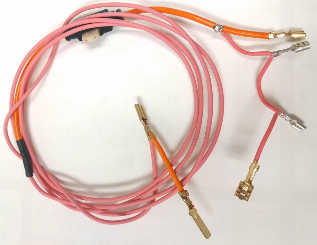
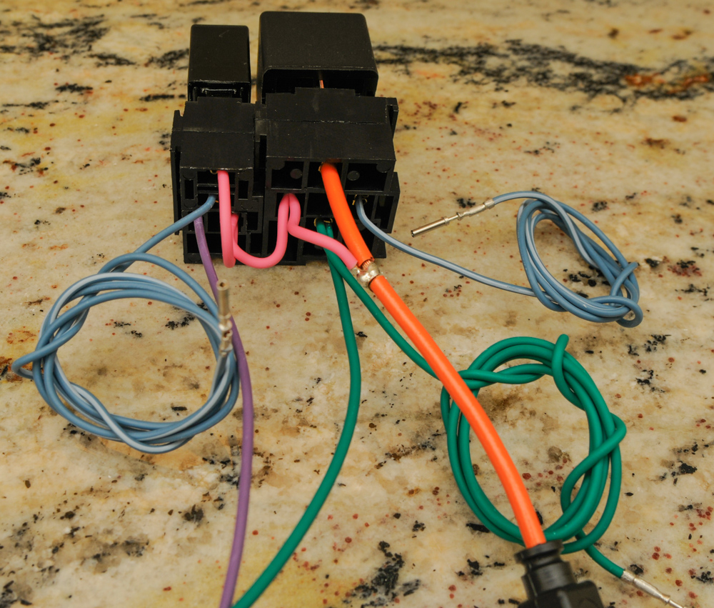
 Step 1 - Build the Power Harness
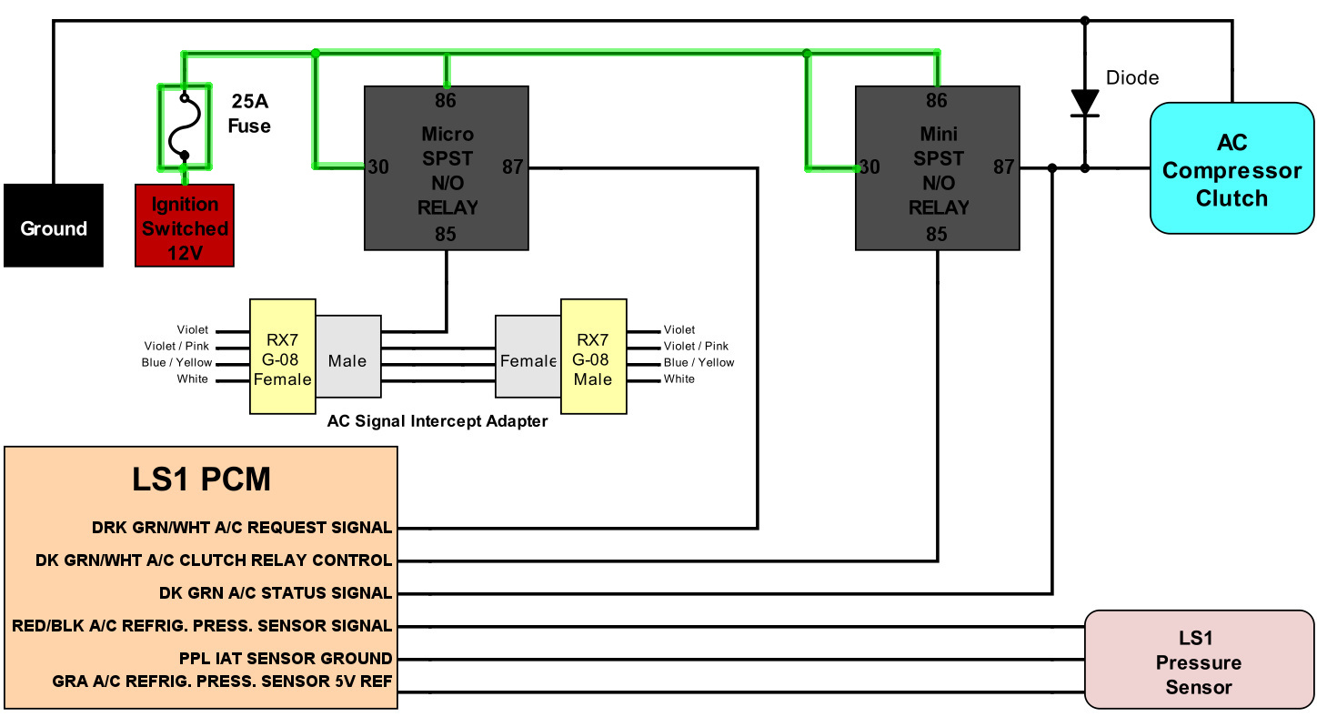
The specifics parts needed are:
6ft Pink 14AWG TXL/GXL wire (main length section)
2in Pink 14AWG TXL/GXL wire (fish-hook / fuse box connection section)
Three lengths of 2 1/2in Pink 18AWG TXL/GXL wire
Mini in-line fuse holder - 46025
Mini 25 A fuse - 46258
.312 Male Terminal = YMST1418L
.312 Female Terminal = YFST1416N
Two Mini relay terminals = 75280
Two Micro relay terminals = 75290
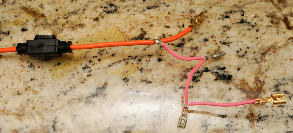
1. On the first end, solder and shrink wrap the 14AWG wire and the fuse holder.
2. On the other end of the fuse holder slice a section exposing bare wire and solder one of the 18AWG wires to it. *Note* Plan and shrinkwrap this connection.
3. At the end of the fuse holder wiring, crimp the Mini relay terminal together with a 2 1/2" Pink 18AWG wire.
4. At the end of the previous 2 1/2" Pink 18 AWG wire, crimp a micro relay terminal along with the second length of 2 1/2" Pink 18AWG wire
5. At the end of the previous 2 1/2" Pink 18 AWG wire, crimp a micro relay terminal along with the second length of 2 1/2" Pink 18AWG wire
6. Finally, at the end of the previous 2 1/2" Pink 18 AWG wire, crimp a mini relay terminal
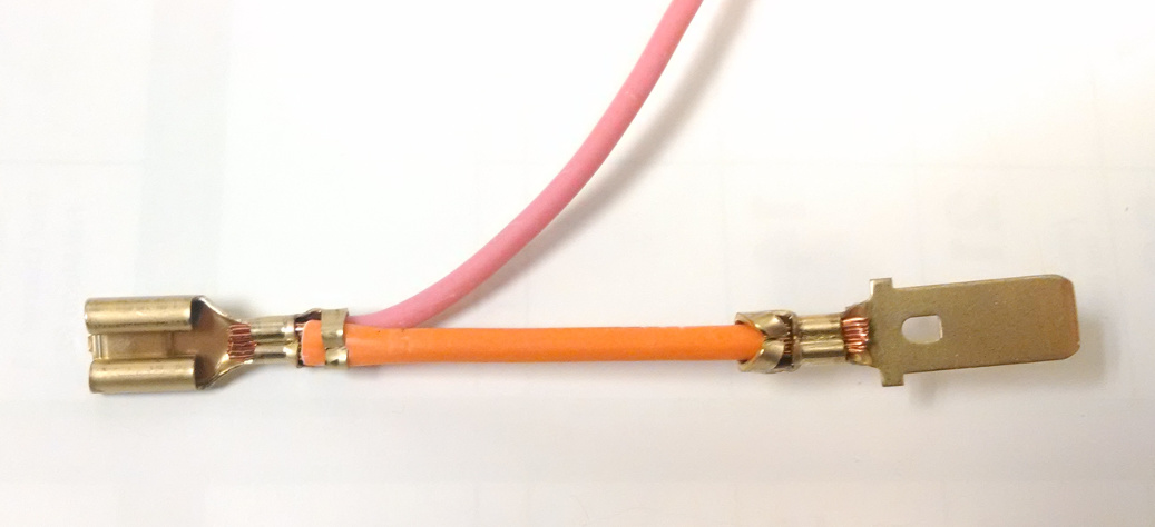
1. On the second end of the 14AWG pink wire, crimp the .312 Male Terminal together with the 2 1/2" pink 14AWG wire.
2. On the other end of the 2 1/2" pink 14AWG wire crimp the female .312 Female Terminal
Step 2 - Build the AC Signal Intercept Adapter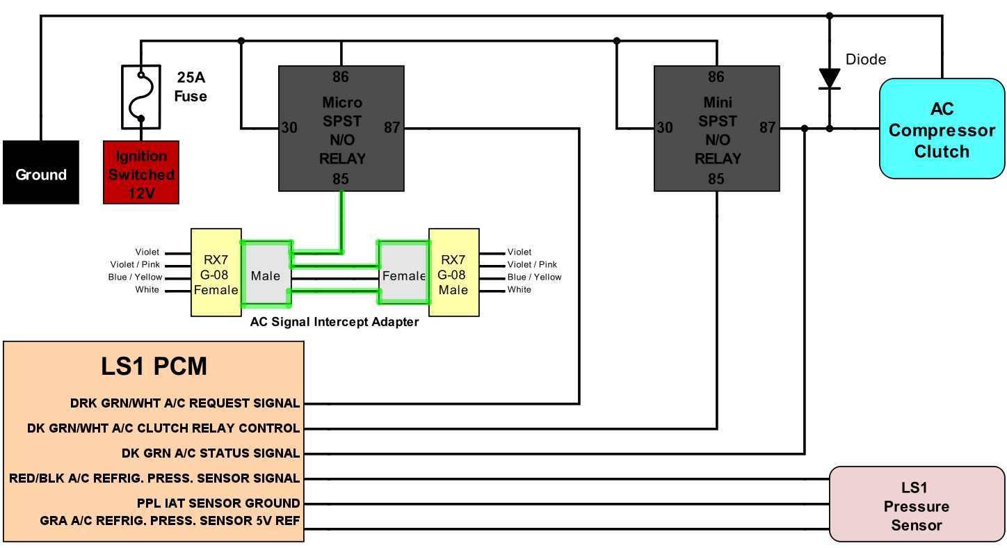
The specifics parts needed are:
3ft Purple 18AWG TXL/GXL wire
3 sections of 2 1/2in gray 16WG TXL/GXL wire
Micro relay terminal -75290
Yazaki CN-A 4 pin Connector Set
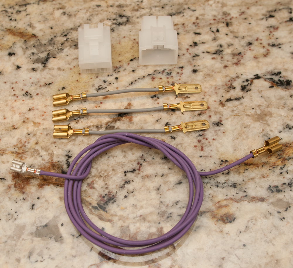

1. Crimp a Yazaki CN-A male and female terminal on each of the 3 sections of 2 1/2in gray 16WG TXL/GXL wire
2. Crimp the Micro relay terminal on one of the 3ft Purple 18AWG TXL/GXL wire
3. Crimp a Yazaki CN-A female on the other end of the 3ft Purple 18AWG TXL/GXL wire
4. Assemble
exactly as shown.
Step 3 - Build the Compressor Clutch harness
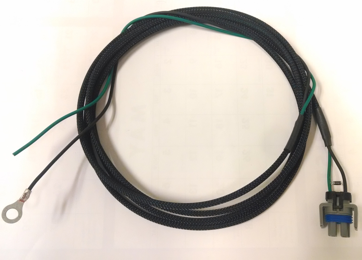 *Note
*Note this tutorial only shows how to build the harness tipped with a connector suitable for a LS1 fbody compressor. If you have a different compressor, you may need a different connector.
The specifics parts needed are:
8ft Black 16AWG TXL/GXL wire
8ft Dark Green 16WG TXL/GXL wire
Two AC Compressor Terminals - 829-12048074
AC Compressor Connector - 829-12162017-B
AC Compressor Connector Lock - 829-12124824-B
Two AC Compressor Connector Seals - 829-15324973
Ground Terminal Ring -31004
One Diode - 512-1N4004

1. Slide the seals on the dark green and black wires.
2. Position the diode so the legs slide through each of the seals and meet the tips of the black and green wire. Note the polarity orientation in the pic and schematic! Note 2 - Involving the the diode makes this a tricky crimping operation. I'd recommend dabbing the crimping section of each terminal with solder if possible to insure the diode is bonded to the terminals.
3. Crimp the terminals on the dark green and black wires.
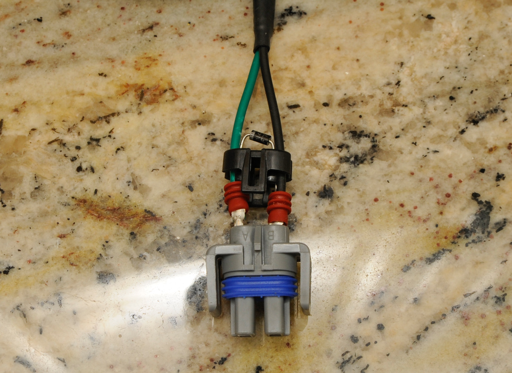
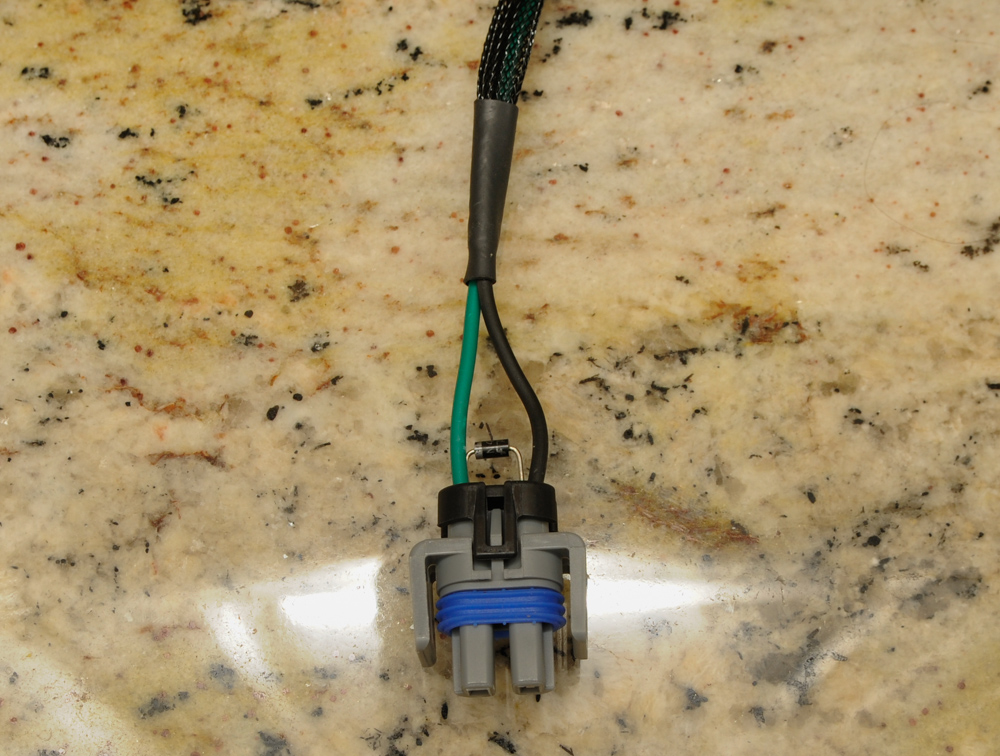
1. Align and press in the terminals and seals in the compressor connector.
2. Sleeve if so desired
1. Crimp the Ground Terminal Ring on the end of the black wire.
2. Leave the dark green wire un-terminated (for now).
Step 4 - Build the Pressure Sensor Harness
The specifics parts needed are:
6ft Gray 18WG TXL/GXL wire
6ft Purple 18WG TXL/GXL wire
6ft Red/Black 18WG TXL/GXL wire
Three PCM Terminals - 829-12084912
Three Pressure Sensor Terminals - 829-12089290
Pressure Sensor Connector - 829-12065287
Pressure Sensor Seal - 829-12065285-B

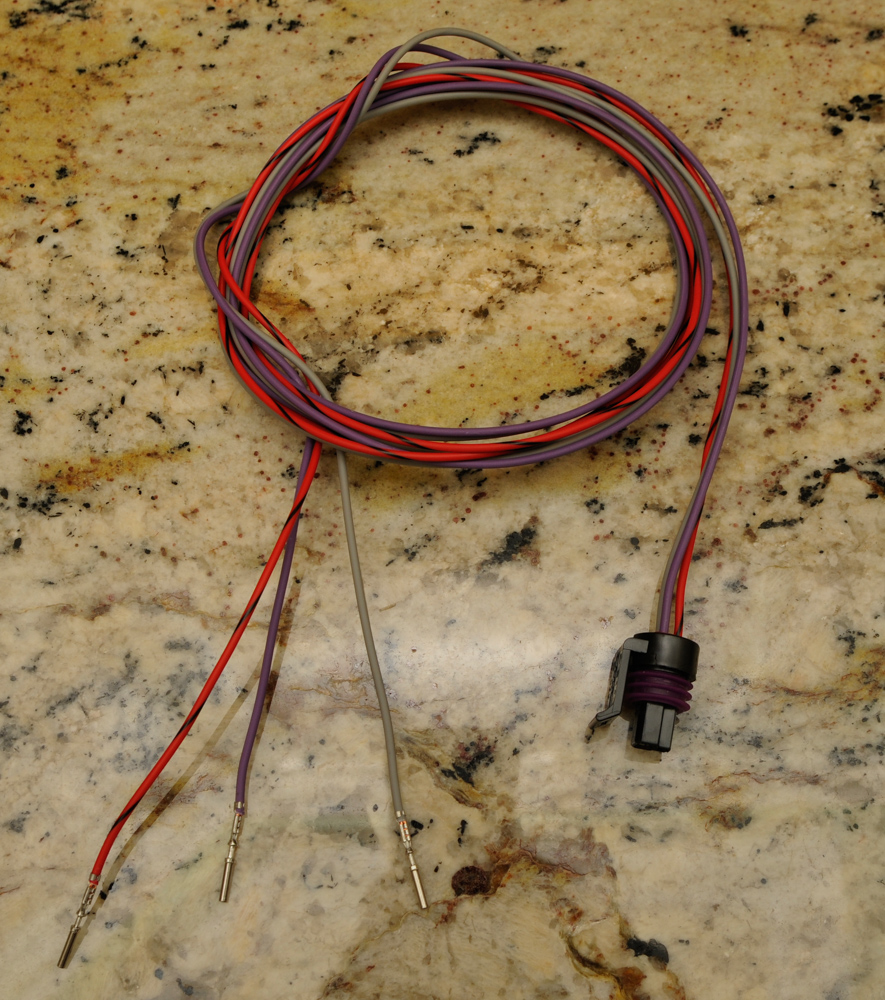
1. Thread the wiring through the seal and connector as show.
2. Crimp terminals on the wire ends.

1. Pull wiring back through the connector until the terminals seat / click.
2. Re seat seal
1. Crimp PCM terminals on the other ends of the pressure sensor wiring.
2. Sleeve wiring if so desired.
Step 5 - Build PCM wiring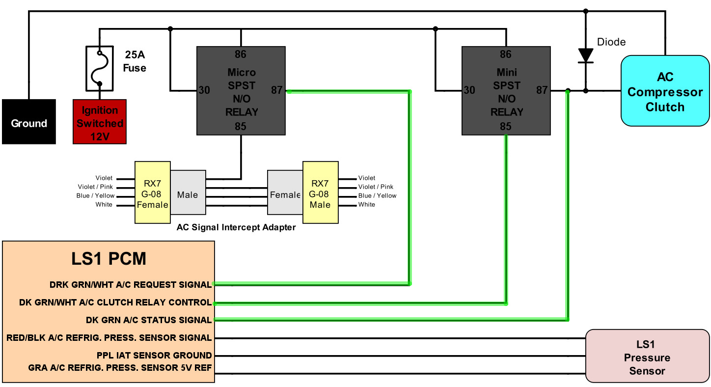
The specifics parts needed are:
2ft Dark Green 18WG TXL/GXL wire
Two Sections of 2ft Dark Green / White 18WG TXL/GXL wire
Three PCM Terminals - 829-12084912
Two Mini relay terminals -75280

*Note* Please make believe that the blue / white wire = Dark Green / White
1. Crimp PCM Terminals to one end of each of the three wires.
2. Crimp Mini relay terminals to the ends of each of the Dark Green / White wires (not shown). Don't crimp anything to the Dark Green Wire yet.
Step 6 - Final Assembly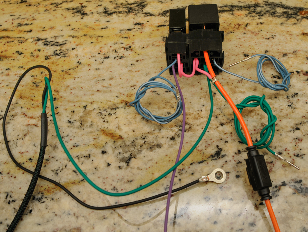
The specifics parts needed are:
Mini relay terminal = 75280

1. Crimp the 2ft 18AWG dark green PCM wire AND the dark green wire of the Compressor Clutch Harness together with a Mini relay terminal
2. Assemble and label the rest of the connections referencing the pictures and diagram above.
3. Install relays
4. Have a beer or 10.
Closing Notes1. You may notice that I sometimes say connect to pin 85 in my schematics and I connect to pin 86 in my pictures or vice versa. Polarity doesn't matter with the relays I've specified so the two are
interchangeable. As long as a ground is on one side and 12V is on the other side, the relay will activate. Pins 87 and 30 are also interchangeable. I just make use of this fact to simplify wiring.
2. If you want to get into the nitty gritty. I don't crimp my seals correctly in the pictures above. The secondary crimp on the terminals is supposed to be used to crimp the seal AND the wire insulation like this:
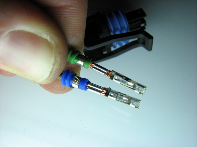
As a amateur I just crimped to the wire insulation as having the seals movable have me a little bit of flex for moving things around like the diode on the compressor connector.
Still, if seals are involved and you want to do it right, try and do it like the picture above shows.
- Lane
