March 19, 2024, 12:07:59 AM

Author Topic: Ultimate AC Line Construction Tutorial - HalfSpec Engineering  (Read 68931 times)

Offline halfspec

Ultimate AC Line Construction Tutorial - HalfSpec Engineering
« on: January 14, 2016, 10:17:25 AM »
*Update* As of 8-9-16 I have sold off all my AC line build materials to mattster03. Matt is taking over the business so if you want to drink a cold beer while Matt builds your AC lines vs you spending hours building them via these instructions, you've got the option now. Message him here if you're interested.

----------------------

As I step back from producing products for the RX7 community I wanted to turn over my designs and convert my projects into a more open source form. This is one of those projects.

Unlike my last DIY AC Line tutorial I am trying to make this tutorial more generic so perhaps the FC guys can get in on the fun. This is still very much geared towards FD owners as all of my build examples will be FD applications, but the parts discussed and theory are universal.

This is going to look intimidating. It’s a ton of information to process. There will be a good bit of you that will take one look at this and want to throw your hands up and curse me for discontinuing my line building service. For those people I would simply say that having someone build you a line kit doesn’t get you out of this work haha! If you were to ask any one of my previous customers I’m sure they’d tell you it was a pain in the ass to get me the data I needed to build their lines. Long story short, no-one, not me, not anyone else, can build a bespoke line kit without working out all the details to make a plan…. Aaannd when that person is building lines remotely, guess who has to gather and understand all that data? ;) So in the end, it may look like big mountain to climb doing this yourself, but really, you’d be doing it anyway buying a kit from me and all you add by doing it all yourself is crimping it all together.

Do NOT simply skip down to the posted example lines kits below and pick out what you think will work for you and go to town. That is a shortcut to a bad time.  Believe me. Do your due diligence and do it right the first time.

Terms of useI am releasing this information freely and you can do whatever you wish with it. All that I ask is that if you do post this information elsewhere, please provide a link back to this thread. As far as support goes, this thread is it. Please don’t PM me with circuit specific or troubleshooting questions. If you have questions, post here and let the very capable community here work it out. If the question can’t be answered by the community I will hop in and answer (I’m subscribed to this thread).

Ultimate AC Line Construction Tutorial

Welcome to revision 2 of my AC Line DIY tutorial. I’m going to divide this section into 6 parts:

1.   System Identification
2.   Component Level Considerations / Pre-Planning
3.   Fittings, Seals, and Tools
4.   Examples of line kits I’ve built
5.   Installation
6.   Charging


AC System Identification:

Before you build a system of lines it is important to identify and know where its components are located:
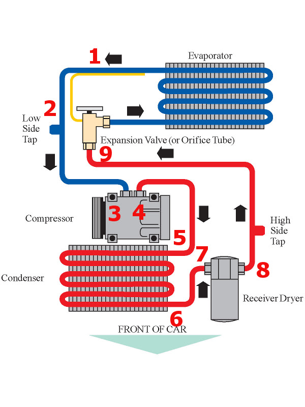

Evaporator – This is the part inside the cabin of the car underneath the dash on the passenger side. In layman terms this is kindof the reverse of a radiator as your liquid refrigerant being sprayed on the inside of the core creates a ‘cold’ radiator which your blower fan blows air through creating cold air.

Blower fan – This isn’t on the diagram but since I mentioned it above I thought I’d talk about it. The blower fan is also almost always located inside the cabin and is always very close to the evaporator. The blower forces air through the evaporator or the heater core depending on your vent selections.

Expansion valve - This valve is generally very close to the evaporator and in some cases is built into the evaporator. Its purpose is to act as a spray nozzle for the high pressure liquid output coming from the drier. The expansion valve restricts flow of the high pressure liquid refrigerant and sprays it inside the evaporator core.

Compressor – The compressor is located on and is driven by accessory belts on the engine. After the liquid refrigerant is sprayed into the evaporator, it converts to a gas and is syphoned away by the compressor. It pulls the gaseous refrigerant from the evaporator and compresses it before sending it on to the condenser.

Condenser – The condenser is located at the front of the car and is cooled with the combination of the radiator fans and forced air at higher vehicle speeds. The condenser takes the hot high pressure gas from the compressor outlet and cools it. The cooling of the condenser causes the gas to condensate and return to its liquid form.

Drier – The drier can be located anywhere between the condenser and the evaporator. It is dual purpose and serves as an oil reservoir as well as a desiccant vessel. The desiccant portion of the drier is where it gets its name and functions by removing the moisture from the refrigerant. This is mostly a 1 time thing as a positively pressurized system should not have moisture leaking in. Therefore the drier simply removes moisture during the first few minutes of operation and once the refrigerant is free of moisture it serves primarily as an oil reservoir.

Service ports – The high service port can be located anywhere between the drier and the evaporator. The low service port can be located anywhere between the compressor and the evaporator.

Component Level Considerations / Pre-Planning

This section is mostly filled with FD specific information I’ve gathered over the years, but while the specifics aren’t universal the concepts should help you avoid pitfalls when planning a line set for any car. You’ll need to plan for every area addressed below. If you need a condenser, buy a condenser. If you need a drier, buy a drier. If you need to make a header change to fit your compressor of choice, make the change. If you need to identify your evaporator, identify your evaporator. You get the idea. Address every area below before you start planning your lines and DEFINETELY before you start ordering parts.

Evaporator – The FD3 RX7 came with two different evaporators. This had something to do with import taxes on cars coming from the manufacturers with AC being brought into the USA in the 90s. Cars with factory AC got taxed more than cars without AC. What you ended up with is some batches of RX7’s being brought into the USA would have factory AC and others would get retrofitted after they made it through customs. The factory AC vehicles included an evaporator and expansion valve combo I refer to as the Denso Evaporator. The vehicles that got retrofitted after customs included an evaporator and expansion valve combo I refer to as the Mana Evaporator. This is important because the Mana and Denso evaporator inlet and outlets are DIFFERENT. You must pre-plan for this. You must know exactly which evaporator you have in order to purchase the correct fittings.

Now, if you search there will be all kinds of ways people have come up with to identify which evaporator you have. Unfortunately a lot of them aren’t 100% accurate. Here 2 inaccurate methods I’ve seen:
1.   If your car is a touring it has a Denso evaporator. Whereas if it’s a Base/R1/R2 it has a Mana evaporator.
2.   You can tell because there are stickers on the outside of the evaporator casing that says Mana or ND (Nippon Denso)

Don’t use the methods above. Some people get lucky, but chances are you won’t if you take the easy way out and don’t do the proper due diligence.
Here is one method that’s accurate but requires that you either have the full working AC system that you disassembled and kept when you removed the rotary or know the full history of the car:
1.   The drier’s hardline connection will identify the evaporator. Denso driers have a hardline that has a sight glass built into the block that bolts to the top of the drier. Mana drier hardlines bolt directly to the drier without a sight glass and the sight glass is further down the hardline built in as a coupler fitting.

The only two methods I know of that are sure fire ways of determining which evaporator is as follows:
1.   Measure the inlet and outlet ports of the evaporator via a thread pitch tool and a caliper or a set of properly spec’d nuts:
        M14x1.5 | 9/16x18 inlet and 7/8-14 outlet = Denso
        M16x1.5 inlet and M22x1.5 outlet = Mana
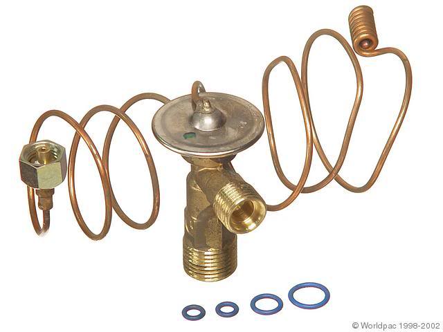
2.   Remove the evaporator from its enclosure box and take a look at the expansion valve.

Denso if it looks like this:

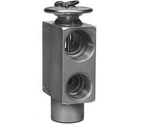
Mana if it looks like this:

Either way, you must know what evaporator you have and know what you’re dealing with before you can begin planning your lines.

Compressor – The compressor is a finicky item to plan for, for two reasons. 1. You’re dealing with placement in a car it wasn’t designed to be in, hence you’ll run into clearance issues you wouldn’t normally have to deal with AND for that simply fact adapters made especially to fit your compressor may not work. 2. Not all LSX compressors have good aftermarket block/adapters. The CTSV LS3 compressor for example has no aftermarket blocks as of the date this tutorial was written. Here are some FD specific notes I’ve gathered over the years related to the use of GM compressors in FD3 RX7s:

1.   LS1 Compressor with rear facing inlet and outlet (inlet/outlet face rear of car). This is 100% supported (with the right headers/exhaust manifold). Just be careful that YOUR engine supports it.   
        I’ve seen folks trying to throw LS1 compressors on LS3 engines which have a drive pulley offset that is incompatible with LS1 compressors. If you’ve got a LS1 compressor and it lines up with 
        your drive pulley, you can relax for the most part (for the most part because headers also play a role (see below)) because you can build on this.
2.   LS2 compressors off of Corvettes and GTO’s with side facing inlet/outlet ports (pointing towards the passenger side) are NOT supported. It’s just too fat of a compressor in a very cramped space
        and there is no way to get any type of adapter in between the compressor and frame rail without major frame rail modifications (I’ve seen it done and it’s not pretty). The good news is that to my
        knowledge LS2 accessories and LS1 compressors are interchangeable so the general solution is to replace the compressor/bracket with a LS1 fbody setup.
3.   LS3 Compressors with side facing inlet outlet ports (pointing towards the passenger side). These are supported but with some caveats.
        a.   LS3 SS Compressors are supported 100% as there are aftermarket adapter blocks
        b.   LS3 CTSV compressors are the caveat. The catch is that there are no aftermarket adapter blocks that I know of that I can buy that are slim enough to fit between the FD’s frame rail and the
                compressor. The SECOND catch is that you can't just swap out the CTSV compressor for a Camaro SS LS3 compressor or LS1 compressor (non compatible accessory spacing) which sticks you
                with the CTSV compressor. Where this leaves us is with the difficult proposition of modifying the stock CTSV adapter lines like keycam and skeltic have done in this thread:
                http://www.norotors.com/index.php?topic=19986.15
                What this involves is cutting the stock CTSV lines short and tig welding new –AN fittings or beadlock fittings on the end of the cut lines. It’s a pain but doable. If you’re willing to do the line
                modification legwork you can procced with using this compressor.
        *Update* - Per 95 Z28 LS3, here is a new option that could possibly solve the issue with using a CTSV compressor in a FD. It's a very expensive aftermarket block, but it's low profile and could possibly clear the FD's frame rail.
4.   LS7 compressors with side facing inlet and outlet ports (facing passenger side). Same story as the LS2 compressor, because, from what cases I’ve seen, LS7 compressor = LS2 compressor.   
        Unsupported due to its hefty OD. The good news is that like the LS2 compressor I believe this can be swapped for a LS1 compressor / bracket.

Almost as important as the compressor itself is the items that are nearby and affect the clearance around the compressor. In this case, the big offender is your headers / exhaust manifold:

1.   JTR Longtubes / Spoolin longtumes = Most clearance and support pretty much any compressor block.
2.   Hooker 8501HKR cast manifold = A tight little config that doesn’t really limit the spacing of the compressor. You should be good for any of the compressor blocks I list later.
3.   LS3 manifolds = Supported but may require heatshield removal / notching for clearance.
4.   2000-2002 LS1 manifolds = Supported but may require heatshield removal/notching for clearance.
5.   1998 LS1 manifolds = Supported but may require heatshield removal/notching AND the EGR casting ridge may have to be ground down for clearance.
6.   Hinson Shorties = NOT supported for LS1 compressors. These dip down directly behind the compressor so that rear facing inlets/outlet have no chance of using an aftermarket block. You can
        modify stock lines that includes a more low profile connection to the compressor but that’s outside of the scope of this tutorial.
7.   Hinson Longtubes = Supported, but I you’re very limited on your options. The reason being is that you’re stuck using a 90 degree block and 90 degree fittings and it’s a ridiculously tight fit
        between the compressor fittings and the headers. People have been able to do it by wiggling them in and/or some grinding, but I don’t recommend it if you have the option.

Condenser – The condenser is a good bit easier to deal with as you don’t really have clearance concerns. The only hard part can come in with mounting the condenser since some radiator options (Hinson, Howe, Mishimoto, etc) don’t have condenser mounts, so in those cases you have to fabricate some type of mounting system for your condenser. When mounting any condenser you will face an orientation decision. Your choice will be to either mount the condenser with the smaller port high (closest to hood) and the larger port low (closest to ground) or the large port high and the small port low. I used to build all my lines with the condenser orientation = small port high, large port low. This created some easier router options and life was good. Since then, I have been advised by someone whose opinion I value that it’s better to orient the condenser small port low, large port high. Apparently the condenser functions a tad more efficiently and you run less of a chance of liquid refrigerant backing up in the lines to the compressor. In my example builds shown in the posts below, you’ll see most of them oriented small port high, large port low. For the purposes of this tutorial I would advise you orient the condenser with the small port low and the large port high. My examples will still be useful, but make a mental note that you’ll need to shorten and extend 2 hoses so you can accommodate the new orientation of the condenser.

Apart from sizing the condenser to your radiator, the only thing you really have to worry about getting right is that the inlets and outlets are something you can work with. Almost every universal / aftermarket condenser I’ve dealt with comes with #6 and #8 male beadlock fittings. More exactly, #6 = 5/8” – 18 male beadlock and #8 = 3/4” – 16 male beadlock. Try and get a condenser that conforms to these standards (shouldn’t be hard) and avoid flare fittings, or proprietary mating system.
Now for FD Specific condenser options you have.

1.   Samberg’s Radiator with CAI. This is simple, just use the condenser he recommends and it will bolt right up:
        http://www.ebay.com/itm/Universal-A-C-Condenser/140277905793?_trksid=p3286.m20.l1116&item=140277905793&pt=Motors_Car_Truck_Parts_Accessories&vxp=mtr
2.   Other. You’ll have to measure your radiator’s core surface area and shop to find a condenser that will take advantage of the area. For example, a LS swap specific Mishimoto radiator has core
        dimensions = 22.2” x 15.75” so you’d probably want to shop around for a 22x15” condenser if you can find it. To do that, just ebay/google “Condenser 22x15” and see what you come up with. I’ll
        go ahead and tell you, you won’t find a 22x15” condenser, but 22x14” is readily available for < $50 and would be a solid choice for a Mishimoto radiator. All you have to do when you get it is
        figure out how to mount it to the front of your radiator. This is usually done by getting your local welder / radiator shop to weld tabs on the front of your radiator. Perhaps down the road this
        thread will fill up with specs of condensers they chose for radiator XYZ but for now you’ll have to do it case-by-case.

Drier – Home stretch! This one is easy I promise! For your drier I would suggest using a 4Seasons 33562. You can get these off of rockauto for $15! It’s an OEM item for older Jeeps and as such is something that’s very easy to find and dirt cheap. It’s sized to be just right for 80s and 90s sports cars. It’s got a built in bracket so it’s fairly easy to mount. Additionally, it has a sight glass built into the connection block above the reservoir. It also has very standard #6, 5/8” – 18 male beadlock fittings for the inlet and outlet. Finally, it has a M10 shrader valve connection which is what the stock GM LS1 pressure sensor adapts to, and what I spec for people to use when designing a LSX controller.

The only difficult part may come in place when mounting it. Ideally, with a LHD USDM spec RX7 you’ll want to mount it on the passenger side of the engine bay between the condenser and the evaporator ports. When I build my kits, this generally boiled down to me mounting the drier to the frame rail right around where the heater inlet/outlet ports are on the LSX engine. The only other point I had to address is that with some radiators, the inlet hose to the radiator crowds the area down by the frame rail making it necessary to raise the drier above it. I generally accomplished this by using a 2” spacer and a 70mm M6 screw to float the drier above the frame rail. You’ll see this reflected in my designs below.

One note I’ll make about the drier while I have the floor is that it will be delivered with caps sealing the inlet and outlet. The caps are there to trap nitrogen which is inside the drier. The nitrogen keeps the vessel pressurized which keeps moisture out. When you remove the caps and the nitrogen comes out, regular air and humidity can get inside the drier and eventually saturate the desiccant. This is bad. This can be avoided by keeping the caps in place until you are ready to actually hook up your lines. You can mock up your drier and do whatever with it. Just don’t remove the caps until you’re ready to install the lines and charge the system

Control – You’ve wired your car with some type of compressor control system haven’t you? If not, don’t worry, I’ve got two more tutorials that can help you:

Ultimate LSX AC Control Tutorial - HalfSpec Engineering
Ultimate LS1 AC Control Tutorial - HalfSpec Engineering

So that’s the component section. Really, that’s the hardest part. Once you get the components of the system settled, the rest is simply getting your fittings sorted out, measuring for your lines then crimping everything together.

Fittings, Seals, and Tools:

These are the most common fittings, adapters, seals, and blocks I kept in my inventory when building LSX FD3 AC lines and what I used them for.


Tools:
To crimp AC lines you need a crimper. I own a Mastercool 71550 which is about the least expensive fitting crimper you can get:
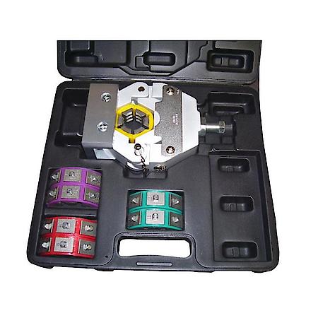

Its survived 4 years of hard use as I’ve used it to build ~ 75 sets of lines. Definitely worth the money.

I also own the following Tekton 6466 PVC cutter:


Technically it’s made to cut through PVC, but it cuts through AC hose like butter so it’s a favorite of mine for getting clean straight cuts.

You’ll also want the following:
1.  Vice grips (to hold onto the crimper)
2.  Socket set / Impact Gun + 19mm socket
3.  Yard Stick
4.  Wax Pencil or other marker than can mark on black rubber hose
5.  Beers

Offline halfspec

Re: Ultimate AC Line Construction Tutorial - HalfSpec Engineering
« Reply #1 on: January 14, 2016, 10:18:01 AM »
Examples of line kits I’ve built

Hopefully this section will makeup for the textbook format of the section above (hooray pictures!)

To start off, I want to go back to this pic:


Here's how the examples below will reference the lines and fittings:

Low Pressure Evaporator to Compressor Hose consists of fittings 1, 2, and 3
High Pressure Compressor to Condenser Hose consists of fittings 4 and 5
High Pressure Condenser to Drier Hose consists of fittings 6 and 7
High Pressure Drier to Evaporator hose consists of fittings 9 and 9


The only tricky hose is the Low Pressure Evaporator to Compressor Hose since it consists of 3 fittings. In the examples below I'll list this hose in two pieces on two rows

So really, once you get your system components straightened out you only have 9 fittings to worry about. Once you get those chosen and mocked up all you have to do is measure, cut your hose, and crimp it all together.


Example #1 - Standard AC Lines using LS1 Compressor + Samberg Radiator (Rev 2/3) / CAI / Condenser

This was my bread and butter design as the samberg radiator takes a lot of the guesswork out of the equation. This design, by default, uses 180º fittings with the compressor which are NOT hinson header compatible, but this design can be modified to use the 90 degree LS1 compressor adapter block + 90º hose fittings. Unfortunately I don't have great pictures, even after making ~50 of these lines because once I took my original pictures I didn't continue taking pics. Here are the reference pics I do have though:


Ignore the annotated measurements. Please see the length measurement sheet below for the measurements I used. Note - I stopped fire sleeving all sections of the lines after my first DIY as it was overkill and affected flexibility. I've since settled on only fire sleeving the top section of the evaporator to compressor hose and the evaporator to drier hose.


An important picture of the low pressure evaporator to compressor hose and the orientation of the fittings


Picture of the high pressure drier to evaporator hose.

Measurements Spreadsheet:


Example #2 - Custom lines using LS1 compressor with Mishimoto radiator and custom mounted samberg condenser

This was an early design I build for gnictry and I believe was my only design that worked around a Mishimoto radiator.


Fitting orientation (be sure to read gnictry's post sale comments in the spreadsheet below).

Here are some actual mocked up pictures:
http://www.halfspec.com/pictures/OpenSource/AC%20Lines/image040_zpsijimtjha.png
http://www.halfspec.com/pictures/OpenSource/AC%20Lines/image038_zpsi6gckc1h.png
http://www.halfspec.com/pictures/OpenSource/AC%20Lines/image036_zpsongyntkj.png
http://www.halfspec.com/pictures/OpenSource/AC%20Lines/image034_zps74o0dztd.png
http://www.halfspec.com/pictures/OpenSource/AC%20Lines/image032_zpsgtmdszkv.png

Measurements Spreadsheet:


Example #3 - AC Lines using LS1 Compressor + Fluidine Radiator + Samberg Universal Condenser

I built this line set for member flattop. I think it actually won the award for the most info passed back and forth getting it all hashed out before I built it. Seriously I wouldn't doubt if our PMs back and forth broke into the triple digits.


More pictures linked for bandwidth purposes:
http://www.halfspec.com/pictures/OpenSource/AC%20Lines/image068_zpssmfcu4ee.png
http://www.halfspec.com/pictures/OpenSource/AC%20Lines/image066_zpspyjfoaop.png
http://www.halfspec.com/pictures/OpenSource/AC%20Lines/image064_zpsznspsrox.png
http://www.halfspec.com/pictures/OpenSource/AC%20Lines/image062_zpsoejhxcrd.png
http://www.halfspec.com/pictures/OpenSource/AC%20Lines/image056_zpsh2fmpkou.png
http://www.halfspec.com/pictures/OpenSource/AC%20Lines/image054_zps7oqhz5n7.png
http://www.halfspec.com/pictures/OpenSource/AC%20Lines/image052_zps0aoo9vkq.png
http://www.halfspec.com/pictures/OpenSource/AC%20Lines/image050_zpsqdmkoomf.png
http://www.halfspec.com/pictures/OpenSource/AC%20Lines/image048_zpslazrbwkg.png
http://www.halfspec.com/pictures/OpenSource/AC%20Lines/image046_zpsr6f0rnkf.png

Measurements Spreadsheet:


Example #4 - Custom lines using LS3 CTSV compressor with OEM custom adapter with brazed on flares facing forward. Mounts to a Samberg Radiator

This is an interesting line build I did for keycam. It's interesting because it's 1 of only 2 line kits I built for someone running a LS3 CTSV compressor. Both people I made these lines for solved their compressor adapter problem the same way. They took the stock CTSV AC lines with the stock adapter, cut the hardlines short, then brazed on ends so that they could be adapted to aftermarket hoses. To date, this is the only viable option I've seen for adapting to a CTSV LS3 compressor.


More pictures linked for bandwidth purposes:
http://www.halfspec.com/pictures/OpenSource/AC%20Lines/IMAG0197_zpsnvfjujkv.jpg
http://www.halfspec.com/pictures/OpenSource/AC%20Lines/IMAG0458_zpsavuc8k8y.jpg
http://www.halfspec.com/pictures/OpenSource/AC%20Lines/IMAG0457_zpspbee2cok.jpg
http://www.halfspec.com/pictures/OpenSource/AC%20Lines/imagejpeg_2_4_zps8vfo6zvw.jpg

Measurements Spreadsheet:


Example #5 - Custom lines using LS3 SS Camaro compressor with CNC'd adapter facing forward. Mounts to a Samberg Rad

This a line kit I built for wickedrx7 that centers around a Camaro SS LS3 compressor. At the time I built this kit I'd built one or two LS3 lines and had optimized the design as I worked through previous builts. I consider this a very good baseline build for someone wanting to build on a SS LS3 compressor. The only thing I'd potentially change is the condenser orientation this kit was built for.


More pictures linked for bandwidth purposes:
http://www.halfspec.com/pictures/OpenSource/AC%20Lines/image098_zpsrsfngzgj.png
http://www.halfspec.com/pictures/OpenSource/AC%20Lines/image096_zpslohyjlor.png
http://www.halfspec.com/pictures/OpenSource/AC%20Lines/image095_zps1sdm57qa.png
http://www.halfspec.com/pictures/OpenSource/AC%20Lines/image094_zpsxyhw3bzs.png

Measurements Spreadsheet:


Example #6 - Custom lines using LS1 compressor with Hinson longtube headers and Hinson radiator and custom condenser

This was a learning build for sure. I built this line kit for FDin7s and it's one of the rare kits I built that centered around a Hinson radiator. Not only that but it was built around Hinson longtubes. Hinson radiator guys have turned out to be a finicky group. I think its possible I only built 1 other kit for a user that was using a Hinson radiator. I talked to plenty of guys running Hinson radiators about building lines, but time and time again, the owners backed off and the lines were never paid for / built. I don't know what that's about. No matter though. I guess the only point I wanted to make was that it's not a design that's very well documented because I haven't done much of it. The hinson radiator doesn't have a good universal mount for condensers so you have to get creative. FDin7s used his stock radiator mounts and some L brackets to mount his condenser...


*Note* Picture posted of lines shows incorrectly attached 180º ends to attach to the compressor. This was actually changed to 90 degree fittings as noted in the fitting list below and mated to a 90º LS1 compressor block.

More pictures linked for bandwidth purposes:
http://www.halfspec.com/pictures/OpenSource/AC%20Lines/image116_zps5u7xospw.png
http://www.halfspec.com/pictures/OpenSource/AC%20Lines/image114_zps8cploecm.png
http://www.halfspec.com/pictures/OpenSource/AC%20Lines/image111_zpsx3sovcrw.png
http://www.halfspec.com/pictures/OpenSource/AC%20Lines/image112_zpsw17syjht.png

Measurements Spreadsheet:


Example #7 - Custom lines using LS3 Camaro compressor with CNC'd adapter facing forward. Mounts to a Custom Radiator
Last example! This is another LS3 line kit I built for Negrok20r that was designed around a Camaro SS LS3 compressor but also added in the curveball of a custom radiator + condenser.


More pictures linked for bandwidth purposes:
http://www.halfspec.com/pictures/OpenSource/AC%20Lines/image126_zpskm6yrjiw.png
http://www.halfspec.com/pictures/OpenSource/AC%20Lines/image128_zps5fhlyxht.png

Measurements Spreadsheet:


- Lane

Offline halfspec

Re: Ultimate AC Line Construction Tutorial - HalfSpec Engineering
« Reply #2 on: January 14, 2016, 10:18:26 AM »
Prep and Installation:

*Note* This is a very generic installation. Its based around my personal AC install with includes a LS1 compressor, JTR headers, Samberg radiator, and the Samberg reccomended condenser.
Also note that this line set is setup with the condenser's orientation = Small port high / Large port low. If you swap this around like I've hinted at above, your installation will be slightly different.


Other Important Notes.
a.   Please read over my topic for prepping a FD for an AC install. Available here:
        http://www.halfspec.com/downloads/rx7/RX7_AC_Prep.pdf
b.   I would advise that you blow out each of your new A/C lines with compressed air.
c.   If you have flushed your old evaporator, condenser, and compressor you have effectively removed all the oil from the system and you will need to add ~ 8oz of PAG 150 oil (for R134a systems)
        or ~5oz of Ester/Mineral oil (for R12 systems) before adding refrigerant.  A/C specialist should also be able to do this before charging. If DIY, oil should be distributed throughout the system and
        can be added to the compressor before reinstalling. It can also be added to hoses A and C after step 5. Additionally, oil can be added to hose D after step 7.
d.   The R134a capacity for this system is ~21oz. The R12 capacity is ~28oz. Do not rely on these measurements though. Use a manifold gauge or have the system charged by a A/C specialist
e.   The drier included in this kit is filled with nitrogen to keep it moisture free. Do NOT remove the sealing caps until you are ready to vacuum down and charge the system. Opening the drier and
        exposing it to the atmosphere will saturate it with moisture in ~ 1hour making it non effective at removing moisture in the A/C system.
f.   Finally, if using a Samberg radiator and his recommended condenser, my lines are built assuming the orientation of the condenser is with the ports facing the passenger side, the small port
        being the highest, and the large port being the lowest.

1.   Install the A/C Compressor block onto the LS1 compressor:


Note – You may be using a 90 degree LS1 compressor adapter (Hinson headers) which looks different from the straight out version show above. The orientation and seal color will be the same. Just remember the larger port (suction) with the red seal installs at the highest point of the compressor.

2.   Move to the top (small) port of the condenser and install hose A and end #1 onto the condenser port with end #2 point upwards and curving back towards the engine bay.


Note – Do NOT connect end #2 to the drier yet as shown in the picture. Just leave end #2 hanging where the drier will be installed on the final step before charging.

3.   Snake the 180 degree ends (some lines may use 90 degree ends) of hoses B and C above and behind the compressor. Install the #1 ends onto the compressor.


4.   While under the car it’s easy to go ahead and connect the compressor’s control plug.


5.   Route hose B parallel with the passenger frame rail, then up and over the frame rail. Finally route it down to the bottom port of the condenser and install end #2.


6.   Route hose C parallel with the passenger frame rail until it gets past the heater hoses, then bend the hose backwards so that end #2 faces the firewall.


7.   Install ends #2 of hoses C and D onto the evaporator lines poking through the firewall right beside and below the ABS pump. This will be the most difficult part of the install. Tip – Unbolt the 3
        bolts holding the ABS pump to the engine bay. This will give you a few more mm of wiggle room. I have always been able to accomplish this task using open and/or adjustable wrenches,
        although I’ve been told stubby open wrenches are an excellent help here. ALWAYS use two wrenches. One to support the factory line’s fitting and one to screw on the new A/C hose end. Not
        supporting the factory line’s fitting will result in permanent damage to the factory line.


8.   Take the bolt, 2 washers, and spacer and assemble them to the drier as shown. *Note* Some designs don't use a spacer.


9.   Position the drier over this threaded boss on the passenger frame rail and screw the drier into place. The drier is made to float 2” above the frame rail using the spacer.


Note – Do NOT remove the caps off of the drier or attach the lines as shown in the pic above until you are ready to vacuum down the system and charge with refrigerant.

10.   At this point the drier will be mounted, but still capped off and hoses end # 2 of Hose A and end #1 of Hose D facing the drier ports.
11.   The vehicle can now be driven to an A/C specialist to be vacuumed down and OR you can DIY.
12.   While at the A/C shop but before letting the A/C specialist charge the system, remove all 3 caps from the drier. You will possibly hear a short hiss when removing the larger 2 caps. This is
        nitrogen being released. After removing the caps, attach end #2 of Hose A and end #1 of Hose B to the drier. Finally, install your pressure sensor onto the small service port of the drier and 
        connect it to your wiring harness.

Charging:

1.    Vacuum the system down to 30 inHg through the high and low AC ports using a A/C manifold / gauge system and a vacuum pump. Alternatively you can get a "Air Vacuum Pump with R134A and
       R12 Connectors" from harbor freight that hooks up to your air compressor to create a vacuum for $16 (Warning, it's a high CFM device).
2.    Vacuum to 30 inHg and close both the low and high pressure valves on the manifold.
3.    If your lines can hold 30 inHg vacuum for 24hrs you're probably leak free and can proceed to charging the system.
4.    Connect a 1lb R134A can to the charge port on the A/C manifolds.
5.    Pierce the R134A can
6.    Purge the line to the R134A can using the schrader valve on the A/C manifold.
7.    Slowly open the LOW side valve on the A/C manifold. This will allow the freon to enter the lines. The can will get very cold. Do NOT try and fill with the R134A can upside down. *Tip* The can, can
       be submerged in hot water (like in a bowl or bucket) to warm the gasses inside the can and help move it into the lines.
8.    After filling for a few minutes to low side of the gauges should read > 30psi which should allow the compressor to kick on. Turn on the car, turn on the AC, and let the system run. Reference
       R134A AC pressure readings for proper operating ranges which should help you decide how much freon you need to add. My pressure readings were 40 / 250 psi on 1lb of freon while the car is
       sitting still while getting cold air output.


- Lane

Offline halfspec

Re: Ultimate AC Line Construction Tutorial - HalfSpec Engineering
« Reply #3 on: January 15, 2016, 12:13:26 PM »
Whew! I think that's it!  :o

I hope the information serves you well. I settled on the 7 examples above because really, they cover just about every oddball situation I ran into. I built a ton of custom lines over the years and documented far more than 7 but I think the ones above should get you through anything you run into.

Feel free to use this thread to bounce ideas off your fellow members. I'll stop by every now and then to answer any outstanding questions, but officially, this post is my exit from the business.

Sometime in the near future I'll have a garage sale to sell off all my spare parts. I'll link to it here when I do.

Cheers  :cheers:
 
Lane


Offline 7th Heaven

Re: Ultimate AC Line Construction Tutorial - HalfSpec Engineering
« Reply #4 on: January 19, 2016, 02:27:50 PM »
You are the man! This is super valuable info. This will make a fun spring project.
Want a FD/FC A/C wire harness? Message me if in need!!  :cheers:

Offline BlinD

Re: Ultimate AC Line Construction Tutorial - HalfSpec Engineering
« Reply #5 on: June 09, 2016, 09:17:24 AM »
And here I was looking for you to build me a set  :D

Phenomenal write-up, looks like it's time to buy some AC line building tools...

93 BB R1 - LS6 Swapped

Offline Skeltic

Re: Ultimate AC Line Construction Tutorial - HalfSpec Engineering
« Reply #6 on: June 09, 2016, 01:51:55 PM »
Thank  you  Lane  you  really  went   beyond  to   help  us   out  with  our  AC  needs.  You are  definitely  the  greatest  guy  to  work  with  on  a  project.
"You can sleep in your car, but you can't race your house."

Offline BlnLs1/rx7

Re: Ultimate AC Line Construction Tutorial - HalfSpec Engineering
« Reply #7 on: July 14, 2016, 06:21:00 PM »
Good information but now my head hurts

Offline Exidous

Re: Ultimate AC Line Construction Tutorial - HalfSpec Engineering
« Reply #8 on: September 09, 2016, 09:51:27 AM »
I would like to make a note about the LS1 compressor and rear fitting. I'm pretty sure that there are plenty of folks where it worked for them but the fitting just isn't right for the LS1 compressor.

The combination of red seal/high side are 0.8mm taller than the green/low side. If you look at Lane's pictures closely you can see the VERY minor height difference. This is causing a vacuum leak for me(testing). At factory tq spec I loose all vacuum in about 30min. Over tightening it gets me to about 5 hours. That's with the vacuum helping the seal. At pressure it'll (and has) leak like a sieve.

If you look at the fitting on http://www.rigidracing.com/2013/09/02/air-conditioning-in-a-240sx-with-an-ls1-swap-the-complete-post/ you'll see the o-ring faces are uneven. The rear facing ones are not and cause this level miss match.

I'm still trying to find a rear facing fitting. If I cannot find one I'll either have the the fitting I do have machined down or do the the 90* block and have the ends of the lines changed.

UPDATE:!!!!!

I found the right one. https://coldhose.com/gm-ls1-style-horizontal-offset-raised-face-compressor-block.html

This is the one I have. https://coldhose.com/catalog/product/view/id/890/s/gm-compressor-horizontal-block-fitting-with-8-and-10-oring-fittings/category/39/ It is NOT for the LS1 compressor.

This is the one Lane lists. https://www.summitracing.com/int/parts/vta-34108-vug/overview/ It has the wrong offset and is meant for the older A6 GM compressors.
« Last Edit: September 09, 2016, 10:13:55 AM by Exidous »
94 BB Sleeved gen IV LS7, MS3ProU with TC, RONIN 8.8 and LT's with custom 3.5"single to VAREX muffler.

Offline halfspec

Re: Ultimate AC Line Construction Tutorial - HalfSpec Engineering
« Reply #9 on: September 09, 2016, 10:17:20 AM »
I would like to make a note about the LS1 compressor and rear fitting. I'm pretty sure that there are plenty of folks where it worked for them but the fitting just isn't right for the LS1 compressor.

The combination of red seal/high side are 0.8mm taller than the green/low side. If you look at Lane's pictures closely you can see the VERY minor height difference. This is causing a vacuum leak for me(testing). At factory tq spec I loose all vacuum in about 30min. Over tightening it gets me to about 5 hours. That's with the vacuum helping the seal. At pressure it'll (and has) leak like a sieve.

If you look at the fitting on http://www.rigidracing.com/2013/09/02/air-conditioning-in-a-240sx-with-an-ls1-swap-the-complete-post/ you'll see the o-ring faces are uneven. The rear facing ones are not and cause this level miss match.

I'm still trying to find a rear facing fitting. If I cannot find one I'll either have the the fitting I do have machined down or do the the 90* block and have the ends of the lines changed.

UPDATE:!!!!!

I found the right one. https://coldhose.com/gm-ls1-style-horizontal-offset-raised-face-compressor-block.html

This is the one I have. https://coldhose.com/catalog/product/view/id/890/s/gm-compressor-horizontal-block-fitting-with-8-and-10-oring-fittings/category/39/ It is NOT for the LS1 compressor.

This is the one Lane lists. https://www.summitracing.com/int/parts/vta-34108-vug/overview/ It has the wrong offset and is meant for the older A6 GM compressors.

Patrick

While I agree that the raised face fitting you linked is something you can use with the LS1 compressor, I don't agree that the fitting I suggest is wrong, or not for the LS1 compressor.

The raised face fitting you linked was created simply so the end user can use it with equal thickness seals. It's a great block. I used it on my first set of lines. It works. But... It's not the only correct solution.
The flat faced fitting I suggest is made to be used with offset thickness seals. The idea being that you can match the seals with your application. In this case, you use the thicker green seal to offset the lack of a raised fitting face. It's correct and it's how the system was designed to work.

Of the ~50 LS1 kits I created that used this fitting and seal system, you're the first to report a leak at the compressor. I don't think that's enough evidence to use absolute terms saying it's wrong for the compressor.

If I had to guess, you've either got a out-of-spec seal, a damaged seal, or a damaged seal face.

Lane
 

Offline Cobranut

Re: Ultimate AC Line Construction Tutorial - HalfSpec Engineering
« Reply #10 on: November 04, 2016, 11:29:22 PM »
I'm in the middle of installing an MS3Pro on my FD, which has a Halfspec A/C kit installed, with the LS1 PCM controlling the A/C.

The MS3Pro has the ability to control A/C function, and integrate fan control as well, but it needs a simple window pressure switch instead of the pressure transducer used with the GM PCM.

Can anyone point me to a suitable pressure switch for R134a, that will also fit the fitting on the drier?
I assume the drier connector has a Schrader valve, so I can swap switches without losing any refrigerant.

Thanks,
David
1995 FD, 7.0 Liter stroked LS3, T56, 8.8, Samberg kit.

Offline halfspec

Re: Ultimate AC Line Construction Tutorial - HalfSpec Engineering
« Reply #11 on: November 05, 2016, 05:47:15 AM »
Can anyone point me to a suitable pressure switch for R134a, that will also fit the fitting on the drier?
I assume the drier connector has a Schrader valve, so I can swap switches without losing any refrigerant.

To my knowledge there isn't one.  I looked hard for one years ago.  It would have definitely been advantageous to only have to deal with one sensor  but I ended up dealing with two and two connections for my ls1 and lsx wiring kits respectively.
Part number for the sensor and the part numbers for building the connector can be found in my lsx controller thread:

http://www.norotors.com/index.php?topic=23631.0

Lane

Offline Cobranut

Re: Ultimate AC Line Construction Tutorial - HalfSpec Engineering
« Reply #12 on: November 05, 2016, 02:26:00 PM »
Lane,

Thanks.

I checked out your link, and ordered the switch from Ryder, p/n MEI 1514.
However, looking at the switch pictures and drawings I could find online, the Metripac connector in your list doesn't seem to match the switch.

From the photos I could find, the switch appears to have a curved internal profile, where the Metripac connector is more rectangular and has a slot for a tab to fit into.

Are you certain this is the correct connector?

Thanks again,
David
1995 FD, 7.0 Liter stroked LS3, T56, 8.8, Samberg kit.

Offline halfspec

Re: Ultimate AC Line Construction Tutorial - HalfSpec Engineering
« Reply #13 on: November 05, 2016, 04:56:38 PM »
Are you certain this is the correct connector?

It's the correct connector, or at least it was < 6 months ago; and looking at the respective parts it doesn't look like anything has changed.

I don't have the parts in front of me anymore as I've sold off most of my stuff, otherwise I'd take a picture for you. You may try reaching out to 7th Heaven if you want to see it working. He may have both on hand and may be willing to snap a pic for you.

Lane


Offline Tictakman

Re: Ultimate AC Line Construction Tutorial - HalfSpec Engineering
« Reply #14 on: November 05, 2016, 06:32:12 PM »
Have you checked Vintage Air for the pressure switch that screws into the dryer?