-
Connector X-14
by
digitalsolo
on 11 May, 2010 11:22
-
Originally posted by Danzan:
IMO, X-14 is the most confusing part of the harness hookup task. this is mainly because the wires change color when going thru the connector.
:dunno: why.
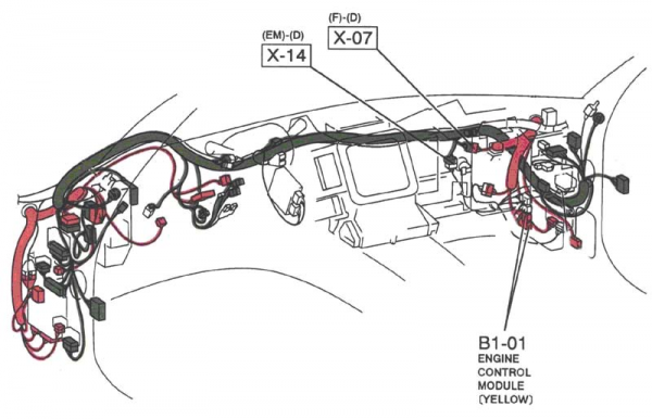
the attached shows the jumper harness plugged into the dasn harness. that connector is X-14.
my instructions reference the wire colors on the jumper harness (emissions) side of X-14. leave the connector plugged in, & cut off the wires, leaving plenty of wire to splice to.
the jumper side of X-14 is the emissions harness. the upper side, is the dash harness.
the 1st pic shows the jumper (emissions) harness plugged into X-14. born-again 7, took this pic.
the 2nd pic shows how the wires change color. if you do not have the jumper harness, you will have to splice into the wires above X-14. they are pretty hard to get to.
i forgot who originated the 2nd pic. there is one error in it. the wire called "green/yellow" on the dash side of the connector, is actually grey.
-
#1
by
SkEdY
on 01 Jun, 2010 18:47
-
I cant see any pictures!
-
#2
by
spayd21
on 18 Jun, 2010 14:02
-
Thank you so much for this post. I do not have the jumper harness and this saved me alot of time..... alot of time.
-
#3
by
AHarada
on 01 Sep, 2010 19:04
-
Here's another picture that might be useful.
The following wires are the colors on the EM side.
O - Orange
Page: Z-42
Description: VSS, ground
G - Green
Page: Z-42
Description: VSS, signal
Y/R - Yellow/red stripe
Page: Z-64
Description: Switched 12V+, from back-up light switch
G/Y - Green/yellow stripe
Page: Z-64
Description: 12V+ (15A - METER), to back-up light switch
Y/W - Yellow/white stripe
Page: Z-42
Description: Water temperature sender
-
#4
by
05_Raven
on 08 Oct, 2010 23:45
-
To gain access to X-14, what needs to be removed?
-
#5
by
Trinh
on 09 Oct, 2010 10:16
-
nothing really, just have to put your hands back there..
-
#6
by
05_Raven
on 09 Oct, 2010 10:30
-
I've removed the glove box and the air conditioning core was loose in the trunk are when I bought the roller.
If I don't have X-14 jumper harness, do i need to pick the coolant temp signal up at X-15 under the driver's side?
-
#7
by
Troux
on 09 Oct, 2010 11:14
-
^You could just buy the X-14 harness that's in the part for sale forum.

-
#8
by
05_Raven
on 09 Oct, 2010 12:54
-
^You could just buy the X-14 harness that's in the part for sale forum.
you got a PM
-
#9
by
Covert5150
on 07 Feb, 2012 19:53
-
I really don't know what to say guys, I'm still having problems with this and Dan's FD harness hookup instructions.
"Water Temperature Gauge: Connect one yellow/black harness wire to the
temperature sender & the other yellow/black wire to the yellow/white."
I left the jumper harness plugged into the dash harness and cut the rest off as the instructions say - But I only have one black/yellow wire.
I have all the lamps across the bottom of the cluster. My fuel level gauge is also working. My odometer is also showing mileage. I'm running into not having any illumination in park/headlights. I also show no RPM while cranking.
Here is a picture of what I have right now:
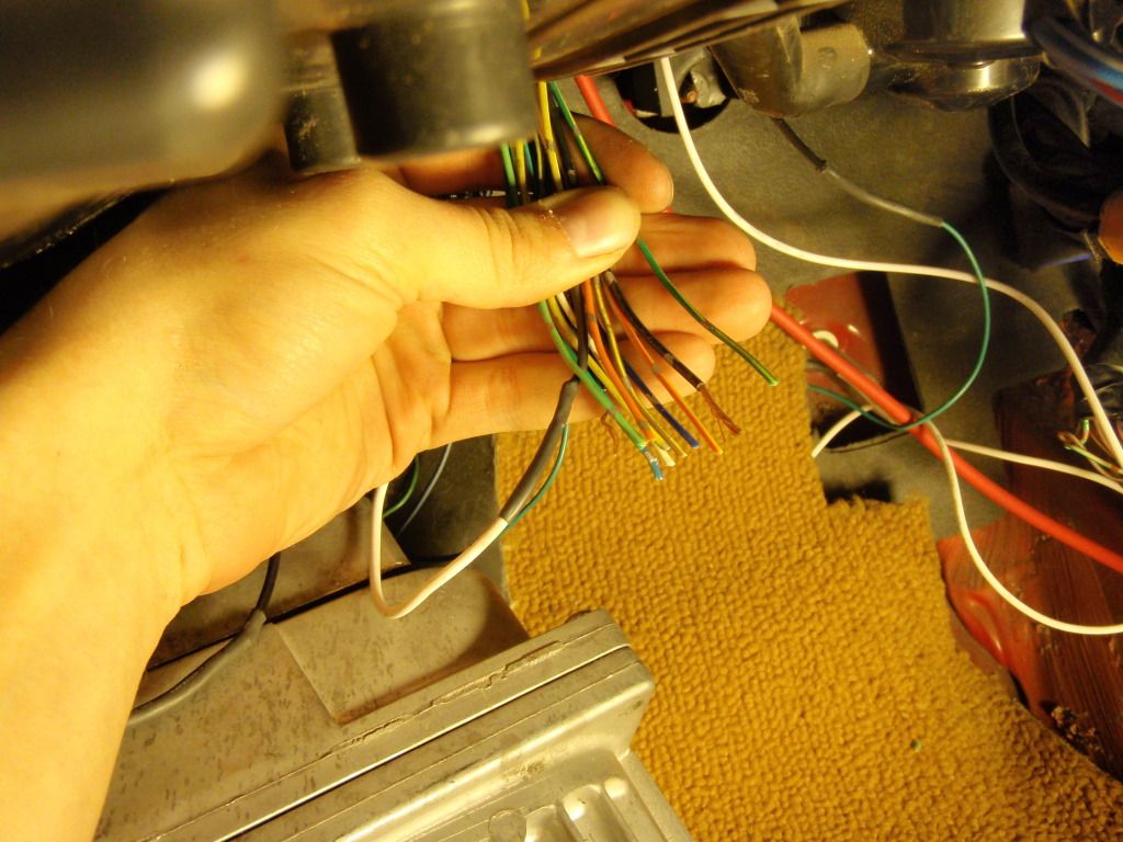
The white wire that is spliced into the yellow/white wire is the coolant temperature from the sensor. I figured I had a missing ground.
I did some research and pulled this up from another thread:
Looks like I have a black/yellow wire and a black with silver dots grounded on mine.
black/yellow is 3rd from top left and black/silver is top right.
[attachimg=1]
I ran a jumper wire straight to battery (-) from both these and neither or both seem to illuminate the backlight.
-
#10
by
halfspec
on 07 Feb, 2012 20:49
-
There's nothing related to X-14 and the the cluster backlights as far as I know. Just make sure your TAIL fuse is alive, your TNS relay is working, your dimmer switch is plugged in and turned on, and that the 2 instrument harness grounds are bolted to the chassis (behind the glove box).
RPM signal to gauge isn't related to X-14 either. I believe it's available at the old yellow ECU connectors.
The water temp sensor is just a resistor. If you check out page Z-44 of the electrical FSM you'll see that the Y/W wire goes to the gauge and the other side of the sensor is connected to the chassis ground. Since you don't have your emissions harness anymore, simply have one of the wires of the temp sensor lead to the Y/W wire at X-14 and the other wire ground to your chassis.
Lane
-
#11
by
Covert5150
on 07 Feb, 2012 21:30
-
Oh jeeze, My dimmer switch wasn't plugged in - Just verified my back light now illuminates.
As far as the tach, it is spliced into the yellow/blue wire on the smaller of the yellow PCM connectors. I just wasn't sure if it would display RPM while cranking.
My ECT is grounded through pin 25 of the blue connector to the PCM. Is it not a voltage divider circuit?
There is nothing else I need to worry about regarding connector X-14? With exception to my dakota digital. I was curious about that post I had quoted in my original post about the 2 wires that Kev had grounded out.
Thanks for the help Lane. you da man.
-
#12
by
halfspec
on 07 Feb, 2012 21:42
-
No prob bro.
Not sure about the tach at crank since my FD doesn't have a stock Tach.
You've talking about two different coolant temp sensors bud, which one are you worried about? The Y/W wire in X-14 goes to the coolant temp gauge and should be hooked to a mazda OE type temp sensor in order for it to function properly. Most people adapt the coolant port on the passenger side of the engine to fit an OE sensor.
The ECT you're talking about in your last post is a coolant sensor for the LSX PCM. It's strictly handled within the LSX harness and does not talk to the FD's gauge at all.
Just a general fyi since my first post may have been a little confusing. The FD temp sensor only has one wire that leads to the gauge and gets its ground through the engine block which is grounded (hopefully) to the chassis.
Lane
-
#13
by
Covert5150
on 07 Feb, 2012 22:10
-
Well, I've clearly made some oversights.
The wire I spliced into for the instrument cluster was the LS1 ECT. The LS1 sensor is a voltage divider circuit - there are three wires going to the thermistor itself. My PCM pin out shows a sensor ground and sensor signal back into the PCM, it looks like I'm missing my 5v reference.
This is odd because when I cut off the pigtail from my f-body harness (the one that is f-body specific), one of the wires from the LS1 ECT was in that bundle. I had just assumed that would go to the gauge.
-
#14
by
ls3_rob
on 30 Jul, 2014 20:58
-
you wouldn't happen to have the emissions and dash side wiring diagram for the automatic fd would you?
It seems that every wire is different colors/locations
thanks to anyone who could help