Here's my
GTO LS2 + T56 (E40 PCM) 1993 FD wiring guide spreadsheet.
(please note Mazda changed colors of wires at whim).
[attach=1]
There are 2 worksheets, one describing connectors and one for the hookup.
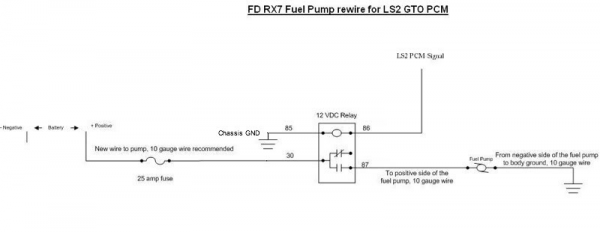
For my fuel pump I did my own direct to power wiring (also known as the "fuel pump wiring mod" on rx7club). Basically you wire a relay that eliminates the stock resistor and pump control crap and gets the power directly from the battery so you get the full 14 volts while the engine is running. (note: the E40 PCM supplies 12V to the relay to turn on the pump). Here is a schematic of the "fuel pump wiring mod" as I implemented it:
For the cooling fan I didn't want to run my own wiring up to the front so I utilized the stock wiring to get power and signal from the PCM to the relay. I removed the relays on the passenger side tower and then tapped into a few of the remaining wires for power and signal from the PCM. My wiring guide doesn't go into detail on that, but it does have the right wires off the PCM for the cooling fan relay coil signal. (note: the E40 PCM grounds the wire to turn on the fan)
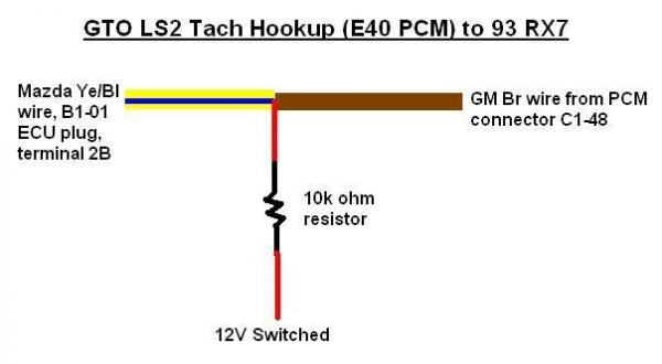
The Tach wiring requires a "pull up" resistor wired in unlike the LS1 wiring. It is described in the wiring guide spreadsheet above, but here is a schematic to further clarify:
I used my guide along with these threads and files (which contain alot of good pics):
Brent_Strong / Dan.Snyder's writeup (Harness hookup with pictures and connector locations):
http://www.norotors.com/index.php?topic=173.0.htmlGranny's instructions:
http://members.tripod.com/~grannys/3LS18.html X-14 connector:
http://www.norotors.com/index.php?topic=225.0.htmlLS2 Helms manual with electrical connectors:
LS2 Forums - Technical Data for LS2, Helms InformationLS2 GTO Electrical / Wiring diagrams
[attach=2]
Also, unless you get the GTO dash harness with your pullout then you will probably need the blue C1 connector. You can buy them here:
EFI Connection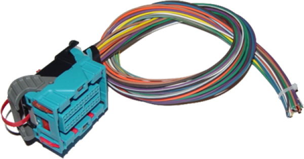
EDIT (11/22/11):
AC wiring and control:
2005+ GM cars (possibly the 04 GTO as well) use both the PCM and BCM for AC control. Since most of the RX7 swaps do not include the BCM we can only use a "manual" AC control (ie not PCM controlled like the Fbody setups). The downsides to "manual" AC control are that you don't get compressor over rev protection, throttle position disable, and idle compensation. LS motors aren't affected much by the added AC compressor load so idle compensation isn't missed. Compressor over rev protection can be created via an RPM window switch set to disable at 4800 RPM and re-enable at 4450 RPM (stock levels according to the EFILive tune file).
I put together a picture of my AC and fan control wiring from memory (I built the car in 07) so please let me know if you see issues.
A word of warning: 93 and 94 AC wiring appears to work differently if I am reading the wiring diagrams correctly. The primary difference is in the positions of the thermo switch and pressure switch in the control lines.
[attachimg=3]
Hopefully its not too confusing. I figure this is better than no LS2 documentation on this site.
- Chris
