Note: This is for an S4 TII FC3S.
S4 Non Turbo and S5 models are similar but not identical.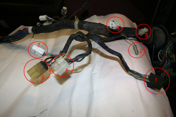
Close up of 6 and 6a

1.
F-03 - Starter Cut Relay
2.
F-39 - Check Connector
3.
F-43 - Condenser
4.
F-34 - Coil w/ igniter
5.
JC-01 - Ground Joint Connector
6.
F-33 - Main Relay
6a.
F-32 - Main Relay
7.
F-35 - Coil w/ igniter
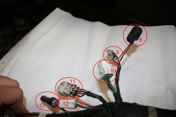
8.
F-20 - Brake Fluid Level Sensor
9.
F-12 - Brake Pressure Switch (Auto Adjusting Suspension)
10.
FE-02 - Connector between front harness and engine harness
11.
FE-03 - Connector between front harness and engine harness
12.
FE-04 - Connector between front harness and engine harness
13.
FE-05 - Connector between front harness and engine harness
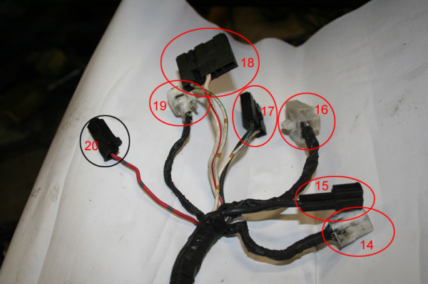
14.
F-29 - Power Steering Stepping Motor
15. Underhood Fuse Box - +12 Constant from main fuse (80/100A)
16.
F-14 - Actuator (Auto Adjusting Suspension) - Left Side
17. Underhood Fuse Box - W/L - EGI Comp (30A), B/G - EGI INJ (40A)
18. Underhood Fuse Box - W/R - BTN (60A), W/G - Retractor (30A)
19.
F-48 - Power Steering Switch
20. Underhood Fuse Box - Headlights (20A)
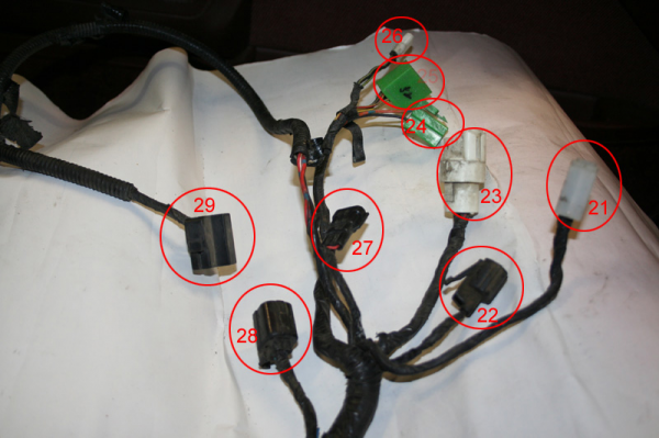
21.
F-28 - Headlight Cleaner Motor
22.
F-44 - Side Marker Light (Left Side)
23.
F-22 - Retractor Motor (Left Side)
24.
F-41 - Check Connector
25.
F-40 - Check Connector
26.
F-36 - Coil w/ igniter
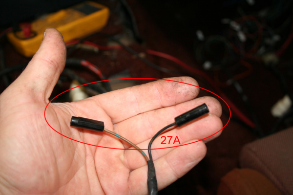
27.
F-46 - Front Parking/Turn Signal Light (Left Side)
27a.
F-37 - Water Temp Switch
28.
F-05 - Front Washer Motor (Left Side)
29.
F-26 - Headlight (Left Side)
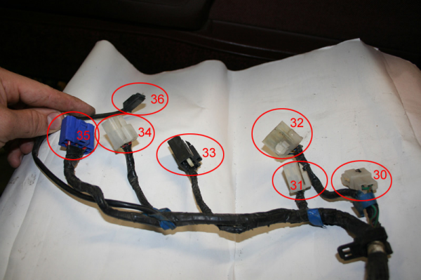
30.
FAC-02 - Connection to Front A/C Harness (AC1)
31.
F-49 - Power Steering Relay
32.
FAC-01 - Connection to Front A/C Harness (AC2)
33.
F-75 - Electrical Fan Relay
34.
F-24 - Headlight Relay
35.
F-25 - Dimmer Relay
36.
F-10 - Additional Horn
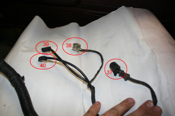
37.
F-74 - Cooling Fan Motor
38.
F-11 - Hood Switch
39.
F-56 - Horn (Left Side)
40.
F-57 - Horn (Right Side)
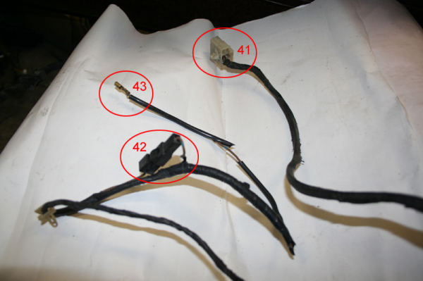
41.
F-13 - Actuator (Auto Adjusting Suspension) - Right Side
42. Disconnect for F-42 (Coolant Temp Sensor) Extension
43.
F-42 - Coolant Temp Sensor
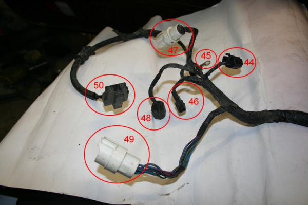
44.
F-45 - Side Marker Light (Right Side)
45. Ground
46.
F-47 - Front Parking/Turn Signal Light (Right Side)
47.
F-23 - Retractor Motor (Right Side)
48.
F-06 - Front Washer Motor (Right Side)
49.
F-09 - Fuel Pump Relay And Resistor
50.
F-27 - Headlight (Right Side)
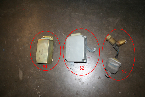
51.
52.
53. Main Relay
------------------------------------------------
Okay, now you know what is what. What I do now is go through and clip all the connectors (leaving about 3-5" of pigtail or more, just in case I need it after all, or to sell on the 'club). I then unloom the entire harness and feed the wires back to their source. If they "T" into another lead, and that lead is in use, I just clip at the "T" and tape it off to insulate it.
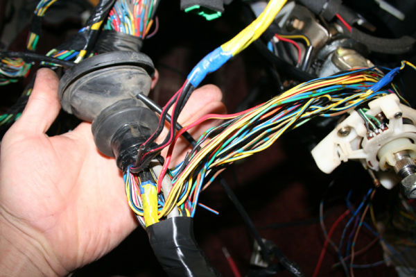
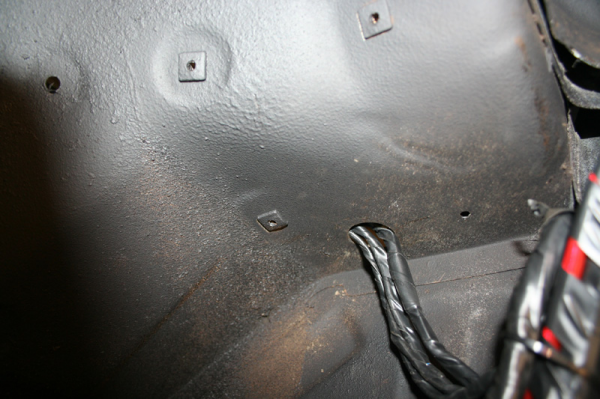
Here's a shot of the leads stripped back to the grommet. After this I pulled them through the grommet and clipped them at their sources to clean up the harness a bit more.
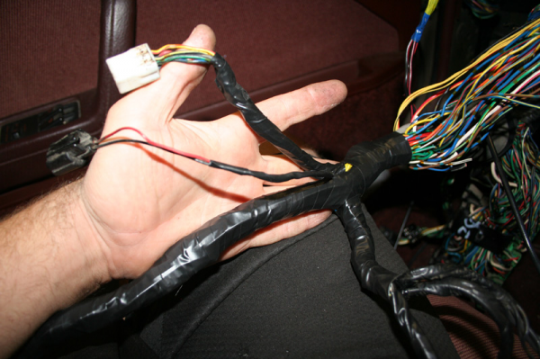
And here is the cleaned up harness, rewrapped with fresh tape:
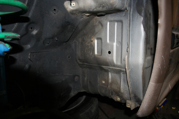
Now, to get the wires out of the cabin and into the engine bay...
Mazda, in their constant accidental foresight put a nice little hole to mark where to cut. It's the hole in the silver area that corresponds with the footwell on the interior. There is a small rubber plug here from the factory:
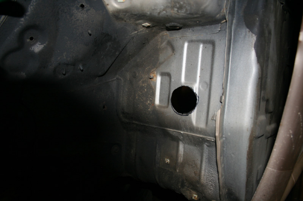
Here it is after trimming it to fit the factory grommet. I used an pneumatic body saw for this. You can use a hole saw, dremel, your teeth, etc.
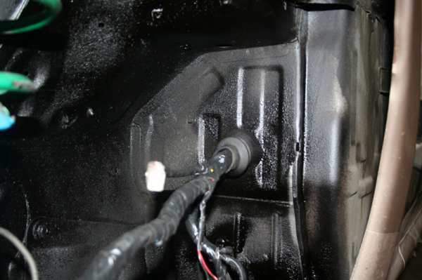
And run through. I still have to add an 8 gauge power lead to power the main fuse box, which is why the grommet isn't taped up yet.
Okay, now you're in the wheel well. Next up, I extended the leads for the low brake fluid indicator, and the leads for the fuse box that used to exist on the driver's strut tower. You'll see in the pictures where I like to locate it after the swap. The only other item that needed extended was the lead for the horns. The factory ground block from the strut tower is grounded to clean metal in the wheel well with a self tapping screw and then sealed with paint.
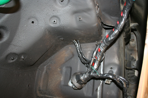
And a close up. This will get a grommet to protect the wires. This is the connection for the LT1 harness injector power and a few other things, cooling fan signal, starter solenoid power and the brake fluid sensor. I don't normally use this spot to connect to the engine harness, but this one was premodded (a Pez unit I believe, it's very nice).
And the front of the fender. As an FYI, over the arch, the harness is zip tied to the top of the wheel arch (under the plastic shield) with a few holes I drilled. These are in the inner structure, not the fender itself).
As you see, the driver's side headlight area plugs (turn signals, side markers, headlights and retractors) plug in here, instead of under the headlight area. You could extend all of these to put them in the factory spot, but I don't see any reason to.
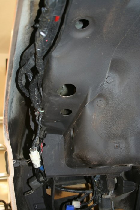
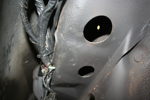
Here is a close up, you can see where the harness enters an existing hole in the inner structure. This comes out behind the headlight and is routed along the front of the chassis to the new fuse block location, and to the horns, passenger side headlight area, etc.
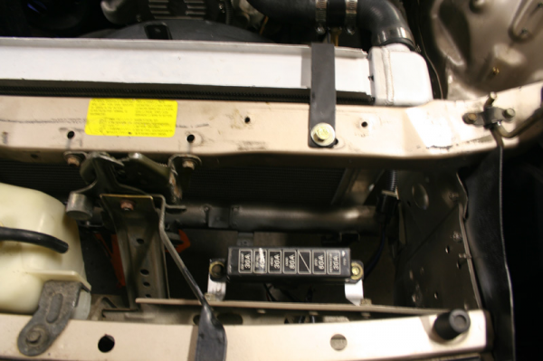
And the new fuse location:
That's really all there is to it. This takes me about 8-10 hours to complete now on an FC, including pulling the dash, but I have a bit of practice. If this seems a bit ambiguous, well, that's on purpose, you can severely screw up your car if you get in over your head here (at least a new front harness isn't expensive!). If you're completely lost here, stop, ask questions, and try to get comfortable before you hack things up. You MUST be able to understand the factory service manual wiring diagrams if you plan on culling connections, or you'll just make your life difficult.
Hope this is helpful. Let me know if you have any questions.

