This thread has been updated and this info is now obsolete. You can find the new tutorial here:http://www.norotors.com/index.php?topic=23657.0- Lane
VERY important notes:These instructions are not meant to help you start a business selling A/C lines to compete with our board sponsors. If I wanted that to happen I could have done it myself and made some extra money on the side. Instead I am giving these instructions away for free in the spirit of this forum's DIY nature.
This project is NOT easy. It requires a lot of parts and access to a very specialized / expensive tool (crimper). If you have any doubts about your ability to complete this project its probably going to be more of a headache than it is worth and I would be happy to build you a set of lines and set you up with whatever you need. Just PM me for a quote.
These instructions are written specifically for the FD3 touring chassis running a Nippondenso* evaporator, a LS1 A/C compressor, and the universal A/C Condenser Samberg recommends for his Rev 2 radiator + CAI. This also assumes you are using Samberg's Rev 2 radiator + CAI. These instructions cover how to build A/C lines to link the previously mentioned components without ANY of the factory hard lines. This means these lines will connect to the evaporator at the firewall. I don't own factory hard lines so I don't know how to adapt my instructions to use them.
If you have ANY differences in your setup the line measurements and/or fittings WILL change. Even if your setup is exactly the same as mine, take my hose measurements with a grain of salt. If you want your lines to look factory, you need to tailor their lengths to your car.
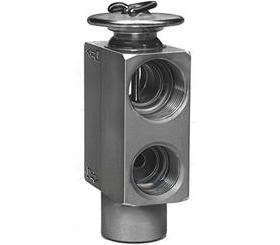
* The FD3 came with two different evaporators. Nippondenso and MANA. Nippondenso has a high pressure inlet of M14 or 9/16x18 and a low pressure outlet of 7/8-14. I only have a Nippondenso evaporator to take measurements on so it is the ONLY evaporator I can recommend fittings for. If someone knows what the MANA fittings should be I can add them to the guide, but for now I can not recommend fittings for a MANA evaporator. To find out which evaporator you have, you can either measure the input and output size and thread pitch or you can disassemble the evaporator box and look at your expansion valve.
Nippondenso's expansion valve looks like this:
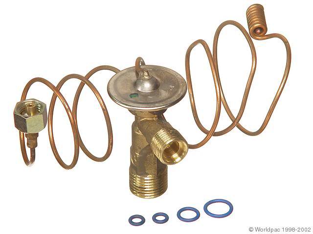
MANA's expansion valve looks like this:
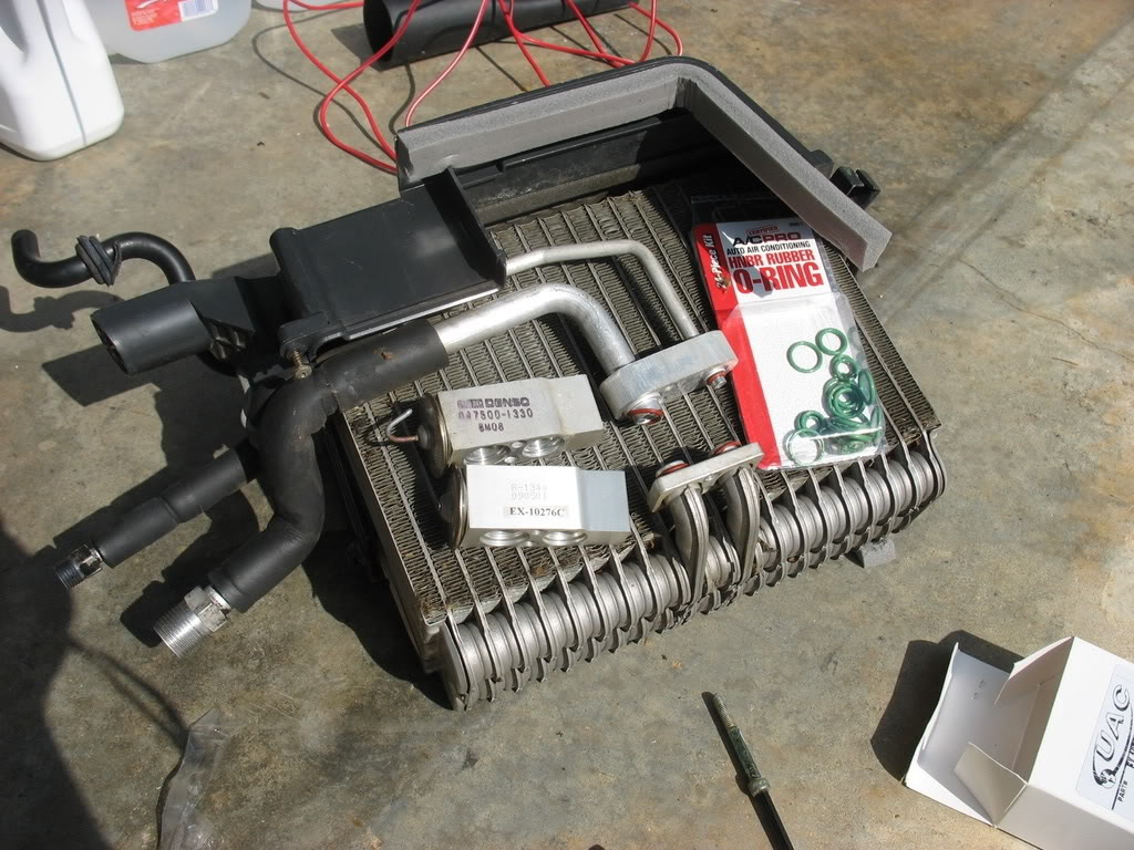
This is a picture of my dissasembled evaporator box with two Nippondenso expansion valves sitting on top of it (I was replacing an old one with a new one):
If you have a MANA evaporator you're going to have to figure out your own fittings at the firewall at least until I get the fitting info and update this guide.
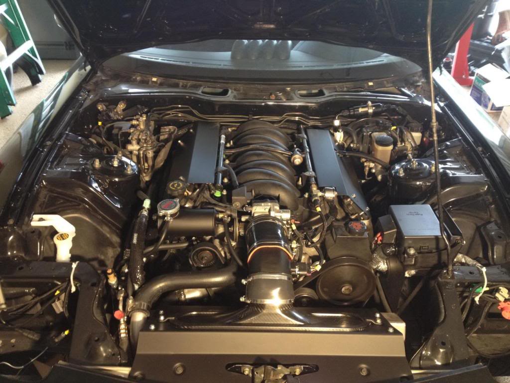
You MUST have access to a beadlock crimper that can crimp #6, #8, and #10 fittings in order the complete these lines. If you don't own one (most likely since they are $200 - $600) contact your local A/C shop about having them crimp the lines.Caveat #3 Updated 4-25-13 - Since writing this tutorial I have since learned that my solution of using a 'straight' LS1 compressor block and two 180 degree fittings will NOT clear stock exhaust manifolds. People running stock manifolds will need to consider other options. I imagine a solution that would fit would be a LS1 Compressor block that is already formed with a 90 degree bend used in conjunction with two 90 degree fittings to make a hopefully much tighter route around the back and to the front of the compressor. Again, do not use a straight LS1 Compressor block and two 180 degree fittings unless you are running JTR longtube headers or an equivalent.Alright. Onto the goods. Here is the final product of what this guide is about:

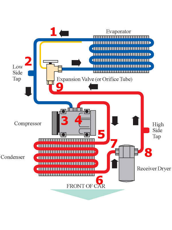
The fittings at numbered so you can match their function to this general AC layout diagram:
 Parts Needed:
Starting with the Evaporator's low side and ending with its high side:
#1 - 7/8-14 Female o-ring fitting with straight angle to #10 hose (Beadlock). This is for the LARGE port on the evaporator. This fitting size will ONLY work for Nippondenso evaporators.
#2 - #10 to #10 hose beadlock splicer with low side R134a fill port
#3 - 7/8"-14 Female o-ring fitting with 180 degree angle to #10 hose (Beadlock). This is for the LARGE suction port on the A/C compressor
#4 - 3/4"-16 Female o-ring fitting with 180 degree angle to #8 hose (Beadlock). This is for the SMALL output / pressure port on the A/C compressor
#5 - 3/4-16 Female o-ring fitting with 45 degree angle to #8 hose (Beadlock). This goes to the LARGE upper port on the universal condenser
#6 - M16x.15 female o-ring fitting with 90 degree angle to #6 hose (Beadlock). This goes to the SMALL lower port on the universal condenser
#7 - M18-1.5 female o-ring fitting with 45 degree angle and custom high side R134a charge port to #6 Hose (Beadlock). This goes to the drier's input port.
#8 - M18-1.5 female o-ring fitting with straight angle #6 hose (Beadlock). This goes to the drier's output port.
#9 - M14-1.5 or 9/16x18 Female o-ring fitting with straight angle to #6 hose (Beadlock). This goes to the SMALL port on the evaporator. This fitting size will ONLY work for Nippondenso evaporators.
Additionally you will need the following:
#10 - LS1 compressor block with #10 inlet and #8 outlet.
#11 - Drier with M18 inlet and outlet.
#12 - 39" of #10 Standard Nylon Barrier Refrigerant Hose
#13 - 22.25" of #8 Standard Nylon Barrier Refrigerant Hose
#14 - 37.25" of #6 Standard Nylon Barrier Refrigerant Hose
#15 - ACDelco 15-5742 Refrigerant Pressure Sensor if you are using your LS1 PCM to control your compressor and you don't already have one.
#16 - Wilmar PN # W5201 - 270 pc o-ring assortment
Purchasing:How about some info on where to buy these parts?

#1 - Alum .A133 ($5.75) # 10 Straight O-ring Fitting -
http://www.coldhose.com/process/add-to-cart.php?pid=5#2 - Alum. A603-3 ($9.49) # 10 (1/2") Inline Splicer w/ R-134a Suction Port -
http://www.coldhose.com/process/add-to-cart.php?pid=256 #3 - Alum. G133 ($10.00) # 10 180 Degree O-ring Fitting -
http://www.coldhose.com/process/add-to-cart.php?pid=53#4 - Alum. G132 ($9.50) # 8 180 Degree O-ring Fitting -
http://www.coldhose.com/process/add-to-cart.php?pid=52#5 - Alum .B132 ($5.50) # 8 45 Degree O-ring Fitting -
http://www.coldhose.com/process/add-to-cart.php?pid=13#6 - Alum. C192 ($7.00) # 6 90 Degree O-ring Fitting -
http://www.coldhose.com/process/add-to-cart.php?pid=143#7 - Alum. B193 ($7.00) # 6 45 Degree O-ring Fitting
http://www.coldhose.com/process/add-to-cart.php?pid=136 #8 - Alum. A193 ($7.00) - # 6 Straight O-ring Fitting -
http://www.coldhose.com/process/add-to-cart.php?pid=128#9 - Alum. A191 ($7.00) # 6 Straight O-ring Fitting -
http://www.coldhose.com/process/add-to-cart.php?pid=126#10 - GM LS1 Style Horizontal Offset Raised Face Compressor Block Fitting - ebay "GM LS1 Style Horizontal Offset Raised Face Compressor Block Fitting AA0442" can be bought from ebay member "airpartsinc" for $30 shipped. Be careful on this part!!! This fitting fits MY LS1 compressor but it may not fit yours. Specifically, this block has a offset raised suction port. Look at your compressor to make sure your large suction port is inset to allow the raised section of the block to mate with it. This fitting comes with it's own seals.
#11 - Drier # 33-0383A or OEM # 12375380 - ebay "Motorhome, RV 00-09 A/C AC Receiver Drier" can be bought from ebay member "airpartsinc" for $33 shipped.
#12 - (ACH10) Standard #10 Refrigerant Hose ($3.99/ft) -
http://www.coldhose.com/process/add-to-cart.php?pid=210#13 - (ACH08) Standard #8 Refrigreant Hose ($3.75/ft) -
http://www.coldhose.com/process/add-to-cart.php?pid=205#14 - (ACH06) Standard #6 Refrigreant Hose ($3.49/ft) -
http://www.coldhose.com/process/add-to-cart.php?pid=200#15 - ACDelco 15-5742
www.amazon.com#16 - Wilmar PN # W5201 - 270 pc o-ring assortment
www.amazon.comWhen I originally wrote this tutorial there was an option to buy #7 with a R134A charge port built in. Since then that source has dried up. Because of this you have two options.
#1 - Buy the parts and have your AC shop weld the charge port to the #7 fitting. For this option you will need to use the following parts:
Alum .WA700 ($4.99) High side weld on charge port - http://www.coldhose.com/process/add-to-cart.php?pid=353
Alum. V101 ($1.99) Core for charge port - http://www.coldhose.com/process/add-to-cart.php?pid=329
#2 - Leave fitting #7 alone and add a #6 splicer to the 23" #6 line (shown in the image above as the line with fittings #8 and #9 attached). This is the same thing I did with the inline fill port (Fitting #2). For this option you will need the following part:
Alum. A601-3 ($9.49) - # 6 (5/16") Inline Splicer w/ R-134a Discharge Port - http://www.coldhose.com/process/add-to-cart.php?pid=249
Either option will work, but you MUST do one of the two.Assembly:The hardest part about assembly is cutting the hoses and crimping the fittings. Cutting the hoses can be done with a angle grinder + a cutting wheel, hack saw, or a chop saw with the appropriate blade. I preferred cutting the hoses with a hack saw while bracing them in my shop's vise.
To crimp you'll need a beadlock crimper that can crimp #6, #8, and #10 fittings. It's pretty much a press that crushes the fittings onto the hose. Check with your local A/C shops for quote to crimp 10 fittings.
Once you've got those two points figured out, just make your lines look like my lines after double checking my lengths to make sure they will fit in your chassis. Also, pay special attention to the orientation of angled fittings. These A/C lines don't really 'twist' at all so make sure you test fit the line and mark the fittings orientation to the hose before you crimp because you can't "undo" a crimp

If you want to wrap the lines in fire sleeve like I did you'll need:
6ft of DEI 010474 1" I.D. x 36" Fire Sleeve and Tape Kit (This works for #8 and #10 hose) -
www.amazon.com3ft of HeatShield 210044 HP Fire Armor Sleeve Black 3/4" ID x 3' Heat Shield Fire Sleeve (This works for the #6 hose) -
www.amazon.comInstallation:Make sure your A/C compressor is oiled and installed. I am not 100% sure about this but a dry LS1 compressor should take 4-6oz of PAG 150 oil.
Here are some pictures of how the lines are laid out:
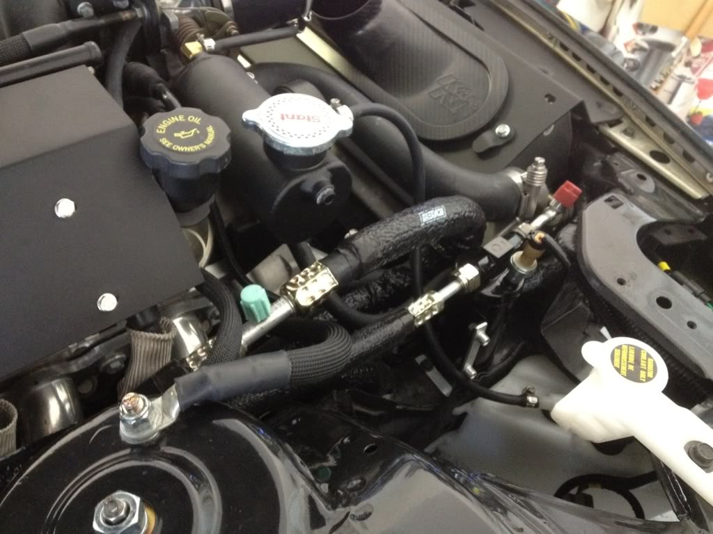

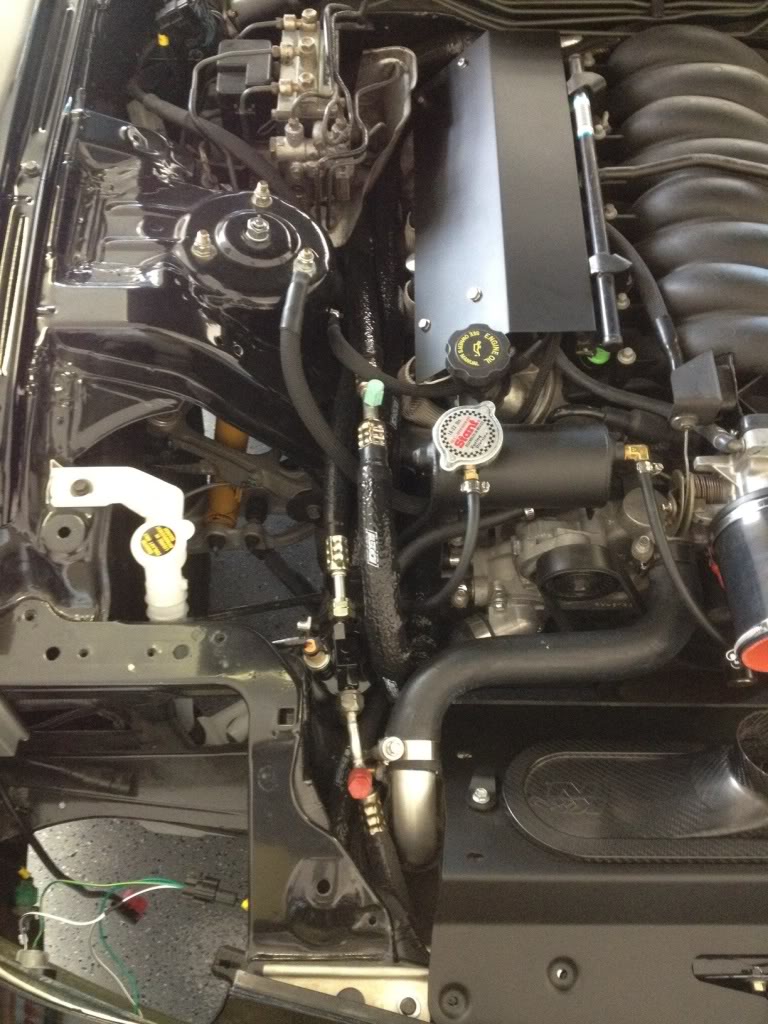

The only part that's going to require additional work is the drier. You will have to make an L shaped bracket to hold it in the position I have pictured. There are several screw bosses in that location you can bolt the bracket to.
Install your o-rings and screw your lines in.
The most difficult part of the install is probably going to be at the firewall and the compressor. Stubby open wrenches will work best here.
Electrical:The LSX PCM and the AC switch use very different signals. so you'll need to use one of the following diagrams based on your setup to get them talking properly:
 This is the diagram to use when the stock fan #1 relay is in place.
 This is the diagram to use when the stock fan relay is removed.
Wanting more information on why the diagrams are different and how the AC request relay translates the signals from the AC switch to something the LSX PCM can understand? Read the excerpt I wrote from another thread below:
----------------
Concentrate on the AC request relay and note the subtle differences between the two diagrams.
Here is how they're different.When you DO have the stock fan #1 relay the AC button gives out 12V when it's not pushed in and GROUND when the button is pressed in.
When you DON'T have the stock fan #1 relay the the AC button FLOATS (like nothing is connected) when it's not pushed in and GROUND when the button is pressed in.
Here is WHY they're different.The AC button connects to the stock fan #1 relay on the ground side of the relay's coil taking a path through the thermo switch, X-07, etc. See pages Z-68 and Z-42 in the FD's electrical FSM. The reason this is significant is that the relay's coil acts as a pull-up resistor. In essence you have a weak connection to 12v through the relay. That's why you see 12v when the button is at rest when fan relay #1 is still connected to it. When the relay is removed/deleted that weak pull-up is no longer there so you get a floating connection. That simple change is enough to redesign the ac request relay circuit.
Alright, pull up Z-68 in the FD's electrical FSM and find the AC switch on the lower right.
Notice that it's normally open. See the leg that exits out of 1G. That's the path to ground. How? You'll see it make its way to position 1 of the blower switch. When you switch the blower switch, this is how it gets ground.
Position #1 = Direct patch to ground through the switch
Position #2 = Path to ground through the diode then to through the switch
Position #3 = Path to ground through the diode then through the second resistor then through the switch
Position #4 - Path to ground through the diode then through the second and third resistors then through the switch
My theory on position 3 and 4 and the resistors is that the resistors are very low resistance (like 1-2ohms so they're negligible). The first resistor is a little more substantial therefore the diode path is there to shortcut it in position 2, 3, and 4.
So, you've got a path to ground through the AC switch on leg 1G. What about Leg 1l?
Leg 1l is the extra tricky one. You'll see it goes through the thermo switch then branches to the fan relay #1 then to the CPU (which is where you Pez's diagram says to pick up the signal at B1-01). Ok so remember the AC switch is
NORMALLY OPEN so it only passes ground when you press the switch. When it's not pressed is what's tricky.
Case #1
Remember what I said about the coil of fan relay #1 providing a weak 12v pullup? Well when the relay is in place, and the AC switch isn't engaged (OPEN) the relay's coil sends 12V to B1-01. Then, when you press the AC switch and the blower is at least turned to position 1 you get a GROUND to B1-01. That describes the scenario in Pez's first diagram. What people get confused about here is the 12V pullup through the fan relay #1. That 12V doesn't just go away so what happens to it? Well that's the concept that makes pullup resistors useful. When you've got a STRONG ground through say the AC switch it OVERPOWERS the weak pullup through the coil so B1-01 only sees a GROUND. It also activates the coil on the relay, making the relay close and start fan #1.
Case #2
This case is when fan relay #1 has been removed / deleted. The weak pullup to 12V through the coil is no longer there so when the AC switch isn't pushed in (OPEN) B1-01 sees
nothing therefore it just sees an an OPEN AC switch. No voltage, no GND, no nothing. However, the actual switch's behavior doesn't change so you get a strong GND when you press the switch.
----------------
The only modification you will have to make to work with my lines is that the pressure sensor wiring will have to be extended to your new drier which is over the passenger wheel well. This is very simple as it only requires extending 3 wires about 5 ft. The drier has a M10 x 1.25 schrader valve that will accommodate the AC systems pressure sensor.
If you don't want to deal with wiring you're in luck I sell plug and play kits that accomplish this for you. Just PM me for a quote of look out for my group buys
 Charging:
Vacuum the system down to 30 inHg through the high and low AC ports using a A/C manifold / gauge system and a vacuum pump. Alternatively you can get a "Air Vacuum Pump with R134A and R12 Connectors" from harbor freight that hooks up to your air compressor to create a vacuum for $16 (Warning, it's a high CFM device).
Vacuum to 30 inHg and close both the low and high pressure valves on the manifold.
If your lines can hold 30 inHg vacuum for 24hrs you're probably leak free and can proceed to charging the system.
Connect a 1lb R134A can to the charge port on the A/C manifolds.
Pierce the R134A can
Purge the line to the R134A can using the schrader valve on the A/C manifold.
Slowly open the LOW side valve on the A/C manifold. This will allow the freon to enter the lines. The can will get very cold. Do NOT try and fill with the R134A can upside down. *Tip* The can, can be submerged in hot water (like in a bowl or bucket) to warm the gasses inside the can and help move it into the lines.
After filling for a few minutes to low side of the gauges should read > 30psi which should allow the compressor to kick on. Turn on the car, turn on the AC, and let the system run. Reference R134A AC pressure readings for proper operating ranges which should help you decide how much freon you need to add. My pressure readings were 40 / 250 psi on 1lb of freon while the car is sitting still (I haven't had time to drive it yet (will update soon)) while getting cold air output.
I believe that's it

If you have any questions or comments please post them here. I can't handle being asked the same questions over and over via PM so I'm hoping we can straighten out any issues here.
Lane
